# 5. IEC61131-3 Syntax
# 5.1 Introduction to Basic Concepts
Real-time programming functions are implemented with reference to the IEC61131-3 Software Information Model, which describes the interrelationships between software elements, including: configurations, resources, applications, tasks, program units (POUs), and global variables.

Configuration: The configuration describes the characteristics of the programmable control system (a PLC), including the hardware device (CPU module and the IO expansion and communication module associated with it), and the binding relationship between resources and tasks.
Resources: The physical units that can be loaded to execute the application, for example, each CPU in a PLC can be considered a resource.
Applications: There are three types of applications: real-time applications, non-real-time applications, and communication protocol stack applications. Real-time applications can be written in ladder diagrams (LD) or structured text (ST), non-real-time applications can be written in Python, and communication protocol stack applications can set parameters based on configuration pages. Each application in this project corresponds to a separate process.
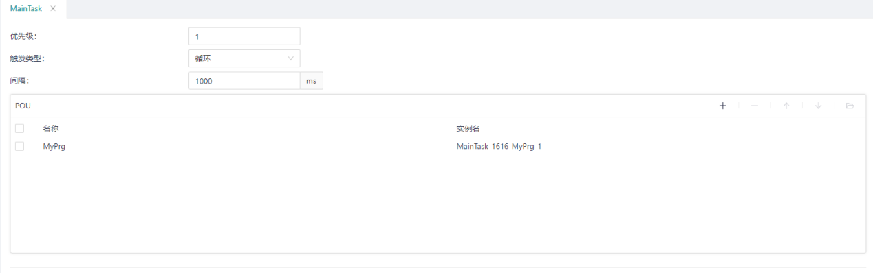
Task: In a real-time application, a program unit (POU) needs to be mounted to a task before it can be executed. Each app can contain multiple tasks, and the order of execution is determined based on the priority of the tasks and how they are triggered. There are two ways to trigger a task: timed loop and event trigger.
Program unit (POU): includes three types: program (PROG), program unit includes function (FUN) and function block (FB), in which the program (PROG) constitutes the main program of the application and can define input and output parameters; The function (FUN) defines the input and output parameters, as well as a function return value, there are no static variables used to save the state, and the same result is always returned for the same input parameters; Function blocks (FBs) define input and output parameters, can save state with static variables, and the result of each execution depends on internal (VAR) and external (VAR_EXTERNAL) variables.
Global Variables & Process Mirrors: Global variables are "global" when they are found everywhere in a real-time application. Different POUs in the same application can interact with data through global variables. In addition, the runtime system will set aside a shared memory area to store the input and output variables in the control process as an intermediary between the application and the IO registers, which is called the process mirror area (storing the variables of the control process), which includes the input variable area (I area), the output variable area (Q area), and the intermediate variable area (M area). When you create a new global variable, you can manually bind it to the process mirror address, and the bound global variable can be accessed by NR applications, NRT applications, and communication stack applications. This project will automatically create a global variable for the protocol object (measurement point) added by the user and bind the process image address.
# 5.2 Common Elements
# 5.2.1 Identifiers
An identifier consists of letters, numbers, and underscores, with the first character being a letter or underscore (not a number) and the last character being a letter or number (not an underscore). Identifiers are not case-sensitive, and abcd, ABCD, or aBCd are treated as the same identifier by the compiler. Consecutive underscores are not allowed in identifiers, for example, __LIM_SW5 and LIM___SW5 are considered invalid.
The IEC61131-3 (2003) standard requires that identifiers should distinguish at least the first six characters, i.e., ABCDE1 and ABCDE2 should be judged to be two different identifiers.
The following are legitimate identifiers
| Identifiers make up the elements | Example |
|---|---|
| Uppercase letters, lowercase letters, numbers, underscores in the middle of identifiers, underscores as first characters | IW215、IW215Z、QX75、IDENT LIM_SW_5、LimSw5、abcd、ab_Cd_MAIN、_12V7 |
# 5.2.2 Keywords
Keywords should not contain spaces and are not case-sensitive, e.g., FOR and for are considered the same keyword by the compiler.
For specific definitions of keywords, please refer to Appendix C of IEC61131-3 (2003).
| Keywords | Description |
|---|---|
| VAR … END_VAR | Variable Declaration VAR CONSTANT LOCALVAR0 : INT := 1; END_VAR |
| VAR_INPUT | Input Variables |
| VAR_OUTPUT | Output Variables |
| VAR_IN_OUT | Input and Output Variables |
| VAR_EXTERNAL | External Variables |
| VAR_TEMP | Temporary Variables |
| VAR_ACCESS | Access Variables (Not Supported) |
| VAR_CONFIG | Configuration Variables (Not Supported) |
| VAR_GLOBAL | Global Variables |
| RETAIN | Qualifier: Hold |
| NON_RETAIN | Qualifier:Non-retaining |
| CONSTANT | Qualifier: Constant |
| R_EDGE | Qualifier: Rising edge |
| F_EDGE | Qualifier: Falling edge |
| READ_ONLY | Qualifier: Read-only |
| READ_WRITE | Qualifiers: Readable and writable |
| TYPE … END_TYPE | Type Declaration TYPE COLOR : (RED, YELLOW, BLUE); END_TYPE |
| STRUCT … END_STRUCT | Structure Type TYPE DEVICE : STRUCT IP : STRING; PORT : INT; END_STRUCT; END_TYPE |
| ARRAY … OF … | Array Type TYPE MEASURE : ARRAY [1..10] OF INT; END_ARRAY |
| AT | Specify the IEC address |
| NOT | Withdrawal |
| MOD | Modular arithmetic |
| AND | and |
| OR | or |
| XOR | Exclusive OR |
| LABEL | Label |
| JMP | Jump |
| PROGRAM … END_PROGRAM | Program Declaration |
| CONFIGURATION … END_CONFIGURATION | Configuration Declaration CONFIGURATION config RESOURCE resource1 ON PLC TASK MAINTASK(INTERVAL := T#100ms, PRIORITY := 1); PROGRAM MY_PRG1 WITH MAINTASK : MYPRG; END_RESOURCE END_CONFIGURATION |
| RESOURCE … ON … END_RESOURCE | Resource Declaration |
| TASK | Mission Statement |
| PROGRAM … WITH … | Task invoker |
| IF … THEN … ELSIF … ELSE … END_IF | IF Sentense IF d < e THEN f := 1; ELSIF d = 4 THEN f := 2; ELSE f := 3; END_IF; |
| CASE … OF … ELSE … END_CASE | CASE Sentense CASE f OF 1: g := 11; 2: g := 12; ELSE g ;= 13; END_CASE; |
| FOR … TO … BY … DO … END_FOR | FOR Sentense FOR h := 1 TO 10 BY 2 DO f[h/2] := h; END_FOR; |
| WHILE … DO … END_WHILE | WHILE Sentense WHILE m > 1 DO N := n / 2; END_WHILE; |
| REPEAT … UTIL … END_REPEAT | REPEAT Sentense REPEAT i := i * j; UNTIL i < 10000 END_REPEAT; |
| EXIT | Exit Sentense EXIT; |
# 5.2.3 Constants
It is declared in the PLC in the form of "type name#value" or "value".
| Type | Description | Example |
|---|---|---|
| BOOL | Boolean | BOOL#FALSEBOOL#0TRUE |
| BYTE | 8 bits,0 ~ 16#FF | 1116#0B2#0000_1011 |
| WORD | 16 bits,0 ~ 16#FFFF | 0 |
| DWORD | 32 bits,0 ~ 16#FFFF FFFF | 16#ABCDEF |
| LWORD | 64 bits,0 ~ 16#FFFF FFFF FFFF FFFF | 16#ABCDEFABCDEF |
| SINT | Short integer,-128 ~ 127 | 125 |
| INT | Integer,-32768 ~ 32767 | -32456 |
| DINT | Double precision integer,-231~ 231-1 | 324534 |
| LINT | Long integer,-263 ~ 263-1 | 545672345 |
| USINT | Unsigned short integer,0 ~ 255 | 1 |
| UINT | Unsigned integer,0 ~ 65535 | 10 |
| UDINT | Unsigned double precision integer,0 ~ 231-1 | 500 |
| ULINT | Unsigned long integer,0 ~ 263-1 | 60000 |
| REAL | 32-bit floating-point type | 1.0 |
| LREAL | 64-bit long floating-point type | 2.0 |
| DATE | Date | DATE#2023-06-29, D#2023-06-29 |
| LDATE | Long date | LDATE#2023-06-29, LD#2023-06-29 |
| TIME_OF_DAYTOD | Time | TOD#11:30:00 |
| LTIME_OF_DAYTOD | Long Time | LTOD#11:30:00 |
| DATE_AND_TIMEDT | Date & Time | DT#2023-06-09-11:30:00 |
| LDATE_AND_TIMEDT | Long Date & Time | LDT#2023-06-09-11:30:000001 |
| TIME | Duration | TIME#1000msT#1d2h7m19s45.7ms |
| LTIME | Long Duration | LTIME#0NS, LTIME#213503D23H34M33S709MS551US615NS |
| STRING | String | ‘text’ |
| WSTRING | Wide String | “text” |
# 5.2.4 Comments
Comments should begin with "(" and end with ")". Nested comments are not allowed inside annotations, for example, (* (*NESTED *) *) is considered a syntax error.
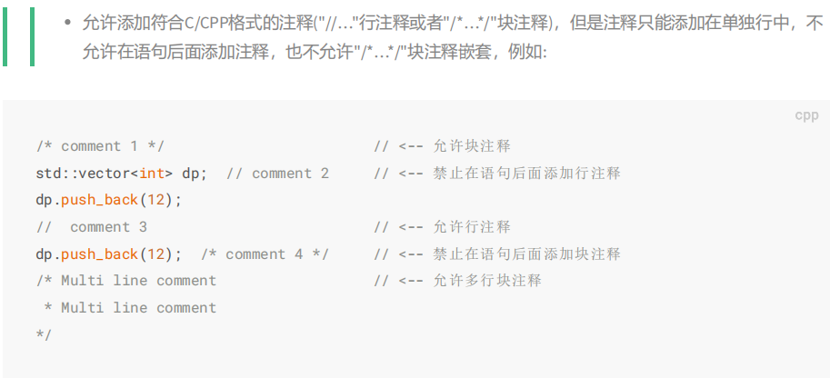
Allow in-line comments starting with //, or block comments starting with /* and ending with */.
# 5.2.5 Preprocessing Instructions
Preprocessing instructions should start with "{" and end with"} ". Example: {VERSION 3.1} {AUTHOR JHC}{x := 256, y := 384}
Currently, the IDE supports the following commands for debugging and printing log information during compilation:
- INFO Example:{INFO: "this is an info message."}
- WAENING Example:{WARNING: "this is a warn message."}
- ERROR Example:{ERROR:"this is an error message."}
# 5.3 Variables
# 5.3.1 Data Type of Variables
# 5.3.1.1 Basic Data Types
The base data types, the keywords for each data type, the number of bits for each data element, and the range of values for each base data type should be shown in the following table. The circumference should be shown in the table below.
| Keywords | Date Type | Bit(N) | Value Range | Initial Value |
|---|---|---|---|---|
| BOOL | Boolean | 1 | 0,1 | 0(FALSE) |
| SINT | Short integer | 8 | [-(2N-1), (2N-1)-1] | 0 |
| INT | Integer | 16 | [-(2N-1), (2N-1)-1] | 0 |
| DINT | Double integer | 32 | [-(2N-1), (2N-1)-1] | 0 |
| LINT | Long integer | 64 | [-(2N-1), (2N-1)-1] | 0 |
| USINT | Unsigned short integer | 8 | [0, (2N)-1] | 0 |
| UINT | Unsigned integer | 16 | [0, (2N)-1] | 0 |
| UDINT | Unsigned double integer | 32 | [0, (2N)-1] | 0 |
| ULINT | Unsigned long integer | 64 | [0, (2N)-1] | 0 |
| REAL | Real number | 32 | -- | 0.0 |
| LREAL | Long real number | 64 | -- | 0.0 |
| TIME | Duration | 32 | -- | T#0ms |
| LTIME | Long duration | 64 | -- | LT#0ms |
| DATE | Date | 32 | -- | D#1970-01-01 |
| LDATE | Long date | 64 | -- | LD#1970-01-01 |
| TIME_OF_DAT or TOD | Time of day | 32 | -- | TOD#00:00:00 |
| LTIME_OF_DAT or TOD | Long time of date | 64 | -- | LTOD#00:00:00.999999 |
| DATE_AND_TIME or DT | Date & time | 32 | -- | DT#1970-01-01-00:00:00 |
| LDATE_AND_TIME or DT | Long date & time | 64 | -- | LDT#1970-01-01-00:00:00 |
| STRING | Single-byte string | 8*N | -- | '' (empty string) |
| BYTE | 8-bit length bit string | 8 | -- | 0 |
| WORD | 16-bit length bit string | 16 | -- | 0 |
| DWORD | 32-bit length bit string | 32 | -- | 0 |
| LWORD | 64-bit length bit string | 64 | -- | 0 |
| WSTRING | Double-byte strings | 16*N | -- | "" (empty string) |
# 5.3.1.2 Custom Data Types (DUT)
By right-clicking on the app and selecting the DUT> you can add a user-defined data type. Currently, 6 user-defined data types are supported, which are:
- Direct Derived Data Type (Alias)
- Enumerate data types (Enumerate)
- Scope Data Type (Scope)
- Array Data Type (Array)
- Struct Data Type (Struct)
- Union Data Type (Union)
# 5.3.1.2.1 Direct Derived Data Types
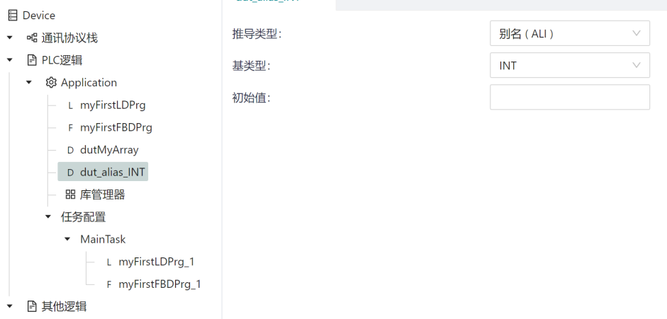
When you declare a direct-derived data type, you can derive a user-defined data type in addition to the underlying data type.
Unless otherwise specified, a direct-derived data type has the same initial value as its derived data type. For example, the derived data type in the following diagram dut_alias_INT used exactly the same way as INT. If you assign an initial value to the dut_alias_INT type in the initial value, the dut_alias_INT type will use the set initial value as the default initial value.
# 5.3.1.2.2 Enumeration
The enumerated data type declares that the value of any data element of that type can only be one of the values given in the list of associated identifiers, which defines an ordered set of enumerated values, starting with the first identifier of the list and ending with the last identifier. Different enumeration data types can use the same identifier as an enumeration value.
To enable the use of unique identifiers in a particular context, enumeration literals can be qualified with a prefix consisting of their associated data type name and the '#' symbol. This prefix must not be used in an enumerated list. If enough information is not provided in the enumeration literal to unambiguously determine its value, a syntax error will occur.
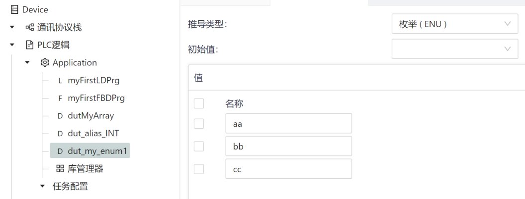
The default default value for an enumerated data type is the first identifier in the enumeration list, or a different enumeration value specified by the user.
For example, dut_my_enum1 the enumeration data type is defined in the following figure, there are three enumeration terms, which are aa, bb, and cc, and their default initial values are aa.
# 5.3.1.2.3 Scope
The scope declaration specifies that the value of any data element of that type can only be between the specified upper and lower bounds. If the value of the range type exceeds the specified value range, it is strictly limited to the range specified by the user.
For range data types, if no initial value is specified, the default default value is the minimum (lower value) of the range.
# 5.3.1.2.4 Arrays
An array declaration specifies that each element of the type is allocated enough data storage space to store all the data that can be accessed through the specified index range.
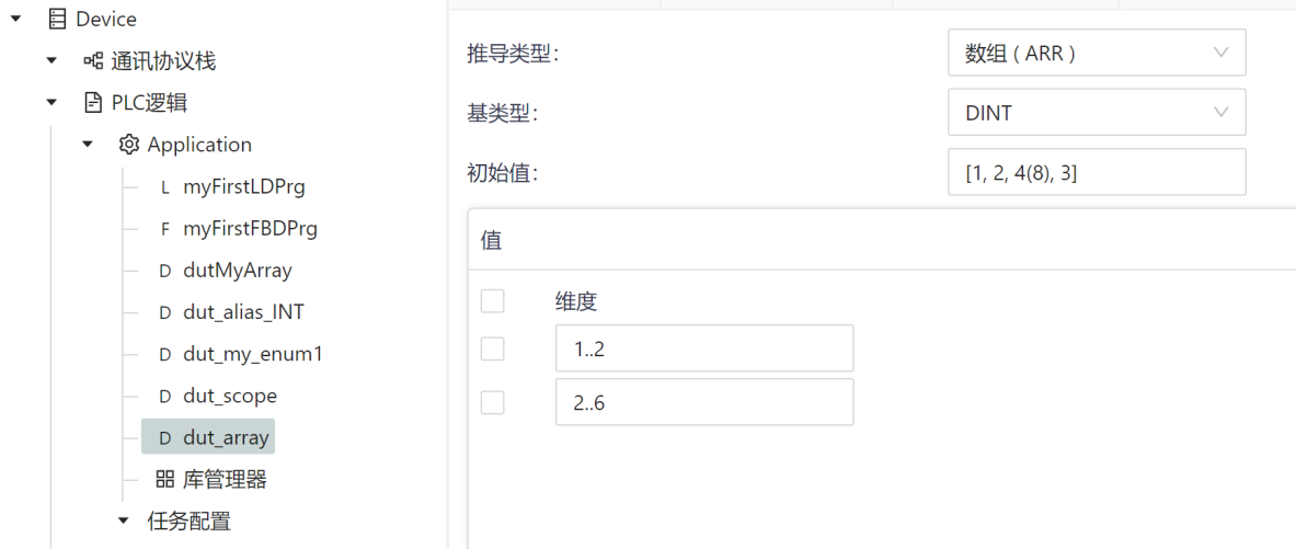
If not otherwise specified, the default value of the array element is the default value of the corresponding data type.
In the following example, a two-dimensional array is defined dut_array, and the following table is 1. 2 and 2.. 6。 The two-dimensional array contains two rows, five columns, and ten elements, as shown in the following table [1,2], [1,3], [1,4], [1,5], [1,6], [2,2], [2,2], [2,3], [2,4], [2,5], [2,6].
Array initialization, which can be initialized in the following way:
- When defining an array, assign an initial value to the elements of the array, for example: [1,2,3,4,5,6,7,8,9,10], then the ten elements will be assigned values from 1 to 10;
- Assign values to only some array elements, e.g. [1, 2]; In this initialization, only the first two elements are assigned, and the array elements that are not assigned are initialized using the default values of their base data types, and in the above example, the last eight elements are initialized to 0;
- For duplicate initial values, you can define them in batches, and you only need to add the number before the parentheses, for example, the element definition of 4(8) in the example above indicates that the value of 4 elements is 8
- When an array element defines an initial value, the parenthesis [] is required to indicate that it is an array structure.
If you only need to define a one-dimensional array, add a dimension.
# 5.3.1.2.5 Structure
The struct declares that a data element specifying that type should contain children of the specified type, which can be accessed by the specified name.
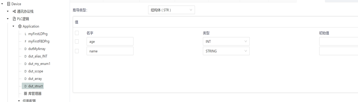
If not otherwise specified, the initial value of the struct element is the initial value of the corresponding element data type.
For example, in the following example, a structure data type is defined dut_struct contains two elements, which are the integer age and the string name. Neither element has an initial value set, so the initial value of its variable type is used as the initial value of the struct element.
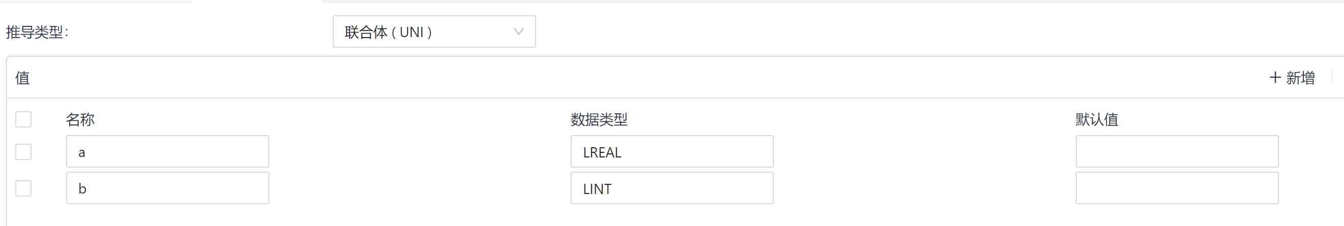
# 5.3.1.2.6 Union
Union is a data structure that usually contains different data types. It is defined in a form similar to a Structure data type.
In a union, all elements have the same offset and therefore the same amount of memory. In the following example of a union declaration, an assignment to the union variable element a. also affects its element b
# 5.3.1.3 Pointer Data Type
# 5.3.1.3.1 Pointer Definition
A pointer stores the memory address of an object (e.g., a variable or a function block instance) at runtime. The syntax is as follows:
<pointer name>: POINTER TO <data type | data unit type | function block>;
 Defining Pointer Types with the POINTER TO Keyword
- Pointers can point to base data types, user-defined data types, or function block types
# 5.3.1.3.2 Example
FUNCTION_BLOCK FB_Point
VAR
  piNumber: POINTER TO INT;
  iNumber1: INT := 5;
  iNumber2: INT;
END_VAR

piNumber := ADR(iNumber1);  // address of iNumber1 assigned to piNumber
iNumber2 := piNumber^;      // assign the value 5 to the iNumber2 variable by pointer deference
2
3
4
5
6
7
8
9
A pointer variable must point to some data in memory before it can be used; if the target has data alignment requirements, it must be ensured that the type to which the pointer refers is the same as the type of data being accessed.
Pointers support both value and address operations:
- Can be taken directly by attaching a content operator to a pointer identifier, such as
piNumber^above.- The
VALfetch instruction can be used to obtain the value of a variable at the address of the pointer and assign it to another variable, similar to using the^symbol to dereference a pointer.- The address value of a variable can be obtained by using the
ADRtake-address instruction to assign it to a pointer, e.g.,piNumber := ADR(iNumber1) above.
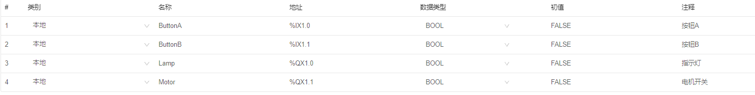
# 5.3.2 Representation of Variables
Variables can be simply divided into two categories, single-element variables and multi-element variables.
A single-element variable is defined as:
- A variable that represents a single data element of one of the basic types;
- Variables that represent enumeration or range types in custom data types;
- A derived data type in a custom data type whose "parent type" is traceable to a base, enumeration, or range type.
Use the identifiers defined in this article as variable symbol representations. Variables can also be associated with an address, in the address bar by the percent sign "%", the position and size prefixes in the following table, and one or more periods (.) Separated unsigned integers are concatenated to form a special symbol.
Directly represents the position and size prefix properties of the variable
| Prefix | Implication | Default data type |
|---|---|---|
| I | Input region | |
| Q | Output region | |
| M | Save region | |
| X | Bit | BOOL |
| None | Bit,ditto | BOOL |
| B | Byte(8 bits) | BYTE |
| W | Word(16 bits) | WORD |
| D | Double word(32 bits) | DWORD |
| L | Long word(64 bits) | LWORD |
The data type of a multi-element variable is an array or a struct.
An array is a collection of data elements of the same data type, indexed by one or more subscripts, enclosed in parentheses ("[]") and separated by commas.
An example of the use of array variables in ST is as follows:
OUTARY[%MB6,SYM] := INARY[0] + INARY[7] - INARY[%MB6] * %IW62;
A struct variable is a variable that is declared as a previously defined struct type, which is a data type consisting of a collection of named elements.
The elements of a struct variable should consist of two or more identifiers or with a single period (.) delimited array access. The first identifier represents the name of the structured element, and the subsequent identifier represents the sequence of component names that access a specific data element in the data structure.
For example, if the variable person is declared as a dut_struct type, the following code will result in 18 elements being assigned to the variable personage; And the name is assigned 'Whoami':
person.age := 18;
# 5.3.3 Variable Declaration and Initialization
Each declaration of a program organizational unit type (each declaration of a program, function, or function block) should contain at least one variable declaration section at the beginning of it, which specifies the type of variable used in the POU (and also the physical or logical location if required).
Variables declare properties
| Type | Keywords | External read and write | Internal read and write | Description |
|---|---|---|---|---|
| Local | VAR | R/W | Variables that are only visible inside the POU | |
| Input | VAR_INPUT | R/W | R | Input form parameter variables. When the called POU uses this type of variable, the arguments are copied (call-by-value), and the value of the arguments will not be changed during the calculation. |
| Ooutput | VAR_OUTPUT | R | R/W | The output parameter variable is used to return the return-by-value result, and the value of the variable cannot be changed after the call is completed. |
| Input and output variables | VAR_IN_OUT | R/W | R/W | The called POU directly uses the call-by-reference of the argument variable, and the calculation process directly changes the value of the argument, so VAR_IN_OUT type variables can be used to pass the calculation result (for array or struct variables, this is more efficient). |
| Temporary variables | VAR_TEMP | R/W | Variables that are only visible inside the POU and are reinitialized each time the program organization unit is executed. | |
| External variables | EXTERNAL | R/W | Used to declare global variables defined in GVL; It can be used in the POU only after it has been declared |
Each variable contains the following properties
- Category: Categorize variables based on their scope
- Name: User-defined, naming conventions should be observed.
- Address: The associated process image address (can not be associated).
- Data types: Basic types and custom types (DUTs) are included.
- Initial value: The user sets the initial value based on the variable type, and the IDE provides the default value.
Notes: User-entered description text that explains the role and use of variables in the program
Variable initialization
When a configuration element (configuration or resource) is started, each variable associated with the configuration element and its program can take one of the following initial values:
- The value of the variable (reserved value) when the configuration element was last "stopped" does not support the reserved property.
- user-specified initial values;
- The default value for the data type associated with the variable
VAR_EXTERNAL is a reference to a global variable and cannot assign an initial value to a variable that VAR_EXTERNAL declares.
During array initialization, parentheses can be used as repeating factors in the array initialization list, e.g., 2(1,2,3) is equivalent to the initialization sequence 1,2,3,1,2,3.
If the number of initialized values given in the initialization list exceeds the number of array entries, the extra (rightmost) initializers are ignored.
If the number of initial values is less than the number of array entries, the remaining array elements are populated with the default initial values for the corresponding data type.
When a variable is declared as a function block instance, the input to the function block and the initial value of any accessible variable can be declared with the assignment operator and the parentheses following the function block type identifier, as shown in the following table. Elements that do not have initial values listed should have the default initial values declared for those elements in the function block declaration.
Initial value assignment of variables
| Feature description/example | |
|---|---|
| Directly represents the initialization of the variable | |
| VAR AT %QX5.1 : BOOL :=1; AT %MW6 : INT := 8 ; END_VAR | Boolean type, initialized to 1 Initializes memory word, value is integer 8 |
| Symbolic variables are initialized with address variables | |
| VAR VALVE_POS AT %QW28 : INT := 100; END_VAR | Assign the output word 28 to the integer variable VALVE_POS with an initial value of 100 |
| Symbolic variable initialization | |
| VAR MYBIT : BOOL := 1 ; OKAY : STRING[10] := 'OK'; END_VAR | Assign a memory bit to the bollean variable MYBIT, with an initial value of 1. Allocate memory to contain strings with a maximum length of 10 characters. When initialized, the string is 2 in length and contains two byte sequences of the character 'OK' (decimal 79 and 75, respectively) in order suitable for printing as a string. |
| Array initialization | |
| VAR BITS : ARRAY[0..7] OF BOOL := [1,1,0,0,0,1,0,0] ; TBT : ARRAY [1..2,1..3] OF INT := [1,2,3(4),6] ; END_VAR | Allocate 8 memory bits to hold the initial value BITS[0]:= 1, BITS[1] := 1,..., BITS[6]:= 0, BITS[7] := 0 A 2 x 3 array of integers with initial values TBT: TBT[1,1]:=1, TBT[1,2]:=2, TBT[1,3]:=4, TBT[2,1]:=4, TBT[2,2]:=4, TBT[2,3]:=6. |
| Struct variable initialization | |
| VAR person: dut_struct := ( age := 18, name := ‘Whoami’); END_VAR | Initialization of a derived data type variable This example shows that the age field for the variable person is initialized as 18 and 'Whoami', respectively. |
| Constant variable initialization | |
| VAR CONSTANT PI : REAL := 3.141592 ; END_VAR | |
| Function block instance initialization | |
| VAR TempLoop : PID := (PropBand := 2.5, Integral := T#5s); END_VAR | Assign initial values to the inputs and outputs of the function block instance |
# 5.4 Program Organization Unit (POU)
The organizational units of a program defined in IEC 61131 include functions, function blocks, and programs.
The program organization unit shall not be recursive; That is, the invocation of a program's organizational unit must not give rise to its own invocation.
# 5.4.1 Functions
A function produces only one data element (considered the function return value) and any number of additional output elements (VAR_OUTPUT and VAR_IN_OUT) when executed. The function return value can be an array or a struct. In a textual language, the call of a function can be used as an operand in an expression.
Functions should not contain internal state information, that is, calls to functions with the same parameters (VAR_INPUT variables and VAR_IN_OUT variables) should always produce the same value (VAR_OUTPUT variable, VAR_IN_OUT variable and function return value). Based on this principle, variables defined in the global GVL cannot be used in functions.
# 5.4.1.1 Function Representation and Declaration
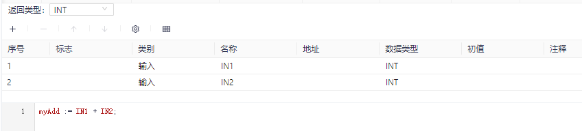
Create a POU by right-clicking on the application-> the POU, selecting the POU type as a function, selecting the programming language used and the return value of the function. For example, the following diagram defines a function named myAdd, which returns the value of the INT data type and writes the function body in ST language.
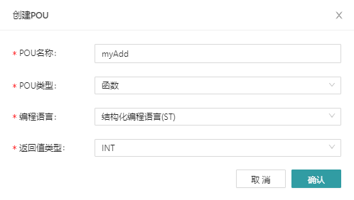
The function name is the return value of the function, so you need to assign the function value at least once in the function definition. The last assignment result is used as the return value of the function. For example, the following figure shows the implementation of a function that has two input parameters, IN1 and IN2, and the function returns the sum of the two input parameters.
There is no need to define additional EN and ENO parameters in the function definition, and the system will automatically generate the corresponding logic.
Functions and how they are called can be represented graphically or literally. The call of the function should follow the following rules:
- The assignment to VAR_OUTPUT variable is either null or variable.
- The assignment to the VAR_IN_OUT parameter must be a variable.
- Assign values to VAR_INPUT parameters can be null, constant, variable, or function calls. In the latter case, the result of the function is used as the actual parameter.
The following diagram illustrates the graph of a function and the use of its equivalent text to call a function, taking the standard function (ADD) as an example.
| Example | Explanation |
|---|---|
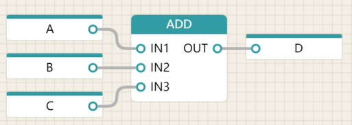 | Use a graphical representation of the ADD function |
| D := ADD(A,B,C); | Textual language using ADD functions (informal calls) |
| D := ADD(IN1:=A, IN2:=B, IN3:=C); | Text language using ADD functions (formal call) |
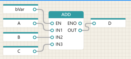 | Execute control of the ADD function graph used |
| D := ADD(EN:=bVar, IN1:=A, IN2:=B, IN3:=C); | Textual language for the ADD function that executes the control (formally called) |
A text call to a function should consist of a function name followed by a list of arguments. In ST, parameters are separated by commas, and the left and right of the list are separated by parentheses "()" . The following requirements must be met:
- Informal calls are not supported in function text language calls with execution control, and can only be called formally.
- In the official call, use the ":=" operator to assign values to input variables and input-output variables
- In the official call, the => operator is used to assign the value of the output variable to the variable
- In the official call, the order of the parameters in the list is not important, and the number of parameters passed is not important, and any variable that is not assigned in the list, if any, uses the default value assigned in the function specification, or the default value of the associated data type.
- The list of informal call parameters should contain the exact same number of parameters, order, and data type as given in the function definition, and do not contain the execution control parameters EN and ENO.
# 5.4.1.2 Function Execution Control Logic
In the function definition, the system provides an additional Boolean EN (Enable) input or ENO (Enable Out) output based on the function declaration, similar to the following definition:
VAR_INPUT AND: BOOL := 1; END_VAR
VAR_OUTPUT ONE: BOOL; END_VAR
When these two variables are used, the execution of the function definition operation is controlled according to the following rules:
- WHEN A FUNCTION IS CALLED, IF THE VALUE OF EN IS FALSE(0), THE OPERATION DEFINED IN THE FUNCTION BODY WILL NOT BE EXECUTED, AND THE ENO WILL BE SET TO FALSE.
- If the value of EN is TRUE(1), ENO will be set to TRUE by the system and the logical operation in the function body will be executed.
# 5.4.1.3 Standard Library Functions
Extensible inputs are allowed for a specified function in a standard function, for example, an extensible addition should have the sum of all its inputs as its output. The actual number of inputs that are valid in the formal call of a function that expands parameters is determined by the formal input name with the highest position in the parameter name sequence. For example:
- X := ADD(Y1,Y2,Y3); is equivalent to X := ADD(IN1 := Y1, IN2 := Y2, IN3 := Y3);
- I := MUX_INT(K:=3, IN0 := 1, IN2 := 2, IN4 := 3); is equivalent to I := 0; Since IN3 has no input, it defaults to 0, and any number multiplied by 0 results in 0.
The function parameters of a standard extensible function follow the following rules:
- If the name of the input variable is not given in the standard function, the default name is IN1, IN2,..., which should be used in the graph from top to bottom.
- When a standard function has only one unnamed input, the default name IN should be used.
- When a standard function has only one unnamed output, the default name OUT should be used.
# 5.4.1.3.1 Type Conversion Functions
The type conversion function should be in the form of *TO , where "*" is the data type of the input variable IN and " " is the data type of the output variable OUT, such as INT_TO_REAL.
Conversions from type REAL or LREAL to type SINT, INT, DINT or LINT should be rounded according to the convention of IEC 60559, according to which the result should be the nearest even number if the two nearest integers are equal, for example:
- REAL_TO_INT(1.6) has a value of 2
- REAL_TO_INT(-1.6) has a value of -2
- REAL_TO_INT(1.5) has a value of 2
- REAL_TO_INT(-1.5) has a value of -2
- REAL_TO_INT(1.4) has a value of 1
- REAL_TO_INT(-1.4) has a value of -1
- REAL_TO_INT(2.5) has a value of 2,
- REAL_TO_INT(-2.5) has a value of –2
The function TRUNC is used to convert the integer portion of a floating-point number represented by REAL or LREAL to an integer, for example:
- TRUNC(1.6) has a value of 1
- TRUNC(-1.6) has a value of -1
- TRUNC(1.4) has a value of 1
- TRUNC(-1.4) has a value of -1
When the corresponding bit-string variables contain data encoded in BCD format, the conversion functions _TO_BCD__BCD_TO_, Dword, and LWORD and USINT, UINT, UDINT, and ULINT variables are executed (respectively). and **). For example, the value of USINT_TO_BCD_BYTE (25) would be 2#0010_0101, while the value of WORD_BCD_TO_UINT (2#0011_0110_1001) would be 369.
# 5.4.1.3.2 Numerical Functions
The following table describes the function name, input and output variable types, and function description of a single numeric variable function. These functions should be overloaded on the defined generic type. These functions, inputs and outputs are of the same type.
| Function | Input/output type | Description |
|---|---|---|
| General function | ||
| ABS | ANY_NUM | absolute value |
| SQRT | ANY_REAL | square root |
| Logarithmic function | ||
| LN | ANY_REAL | natural logarithm |
| LOG | ANY_REAL | Logarithmic base of 10 |
| EXP | ANY_REAL | natural index |
| Trigonometric function | ||
| SIN | ANY_REAL | sine in radians |
| COS | ANY_REAL | cosine in radians |
| TAN | ANY_REAL | tangent in radians |
| ASIN | ANY_REAL | arcsine |
| ACOS | ANY_REAL | arc cosine |
| ATAN | ANY_REAL | arc tangent |
The function name and symbol and description of the arithmetic function of two or more variables are shown in the following table. These functions should be overloaded on all numeric types, and if one of the functions evaluates outside of the range of values specified for the data type output by the function, or tries to divide by zero, a syntax error will occur.
| Function | Sign | Description |
|---|---|---|
| Expandable arithmetic function | ||
| ADD | + | OUT:=IN1+IN2+...+INn |
| MUL | * | OUT:=IN1 *IN2*...*INn |
| Non-expandable arithmetic functions | ||
| SUB | - | OUT:=IN1-IN2 |
| DIV | / | OUT:=IN1/IN2 |
| MOD | % | OUT:=IN1 moeulo IN2 |
| EXPT | ** | OUT:=IN1ᴵᴺ² |
| MOVE | := | OUT:=IN |
# 5.4.1.3.3 Bit String Functions
The function name and description of the shift function of a single bitstring variable are defined in the table. These functions should overload all bitstring types.
| Function | Description |
|---|---|
| SHL | OUT is equal to the left shift of IN by N bits, and the rightmost part is padded with 0 |
| SHR | OUT is equal to IN shifted to the right by N bits, and the leftmost part is padded with 0 |
| ROR | OUT is equal to the right shift of the IN cycle by N bits |
| ROL | OUT is equal to the right shift of the IN cycle by N bits |
The standard graphical representation of the function name, symbol, and description of a bit Boolean function is defined in the following table. These functions should be extensible (except NOT) and overloaded on all bitstring types.
| Function | Sign | Description |
|---|---|---|
| AND | & | OUT := IN1 & IN2 ... & INn |
| OR | OUT := IN1 OR IN2 ... OR INn | |
| XOR | OUT := IN1 XOR IN2 ... XOR INn | |
| NOT | OUT := NOT IN1 |
# 5.4.1.3.4 Select and Compare Functions
The selection and comparison functions should be overloaded on all data types. The following table lists the standard function names and descriptions for selecting a function.
| Graphical Representation | Description/Example |
|---|---|
| SEL | Binary choice: if G = 0,then OUT := IN0, if G = 1,then OUT := IN1, e.g: A := SEL(G:=0,IN0:=X,IN1:=5) ; |
| MAX | Extensible Maximum Function: OUT := MAX (IN1,IN2, ...,INn), e.g: A := MAX(B,C,D) ; |
| MIN | Extensible Minimum Function: OUT := MIN (IN1,IN2, ...,INn), e.g: A := MIN(B,C,D) ; |
| LIMIT | Limit Range Functions: OUT := MIN(MAX(IN,MN),MX), e.g: A := LIMIT(IN:=B,MN:=0,MX:=5); |
| MUX | Extensible Multiplexer Select one of N inputs based on input K, e.g:A := MUX(0, B, C, D);equivalent to A := B |
The standard function names and symbols and descriptions of the comparison functions are defined in the following table. All comparison functions (except NE) should be extensible.
The bitstring data is compared bitwise from the most significant bit to the least significant bit, and the shorter bit string is considered to be filled with zeros on the left side compared to the longer bit string. That is, the comparison of bitstring variables should be the same as the comparison of unsigned integer variables.
| Function | Sign | Description |
|---|---|---|
| GT | > | Decreasing sequence:OUT := (IN1>IN2) & (IN2>IN3) & ... & (INn-1 > INn) |
| GE | >= | monotonic sequence,descending order:OUT := (IN1>=IN2)&(IN2>=IN3)& ... & (INn-1 >= INn) |
| EQ | = | equivalent sequence:OUT := (IN1=IN2) & (IN2=IN3) & ... & (INn-1 = INn) |
| LE | <= | increasing sequence:OUT := (IN1<=IN2)&(IN2<=IN3)& ... & (INn-1 <= INn) |
| LT | < | monotonic sequence,increasing order:OUT := (IN1<IN2) & (IN2<IN3) & ... & (INn-1 < INn) |
| NE | <> | Inequality (non-extensibility):OUT := (IN1 <> IN2) |
# 5.4.1.3.5 String Functions
All functions defined in the previous section apply to strings. In order to compare two strings of unequal length, it should be considered that the shorter string is extended to the length of the longer string on the right by a character with a value of 0. Compare from left to right based on the numeric value of the character code in the character set. For example, the string 'Z' must be greater than the string 'AZ' and 'AZ' must be greater than 'ABC'.
The table lists the standard function names and descriptions for string functions. For the purposes of the operation, the character position in the string should be treated as numbered 1, 2、...,L, starting with the leftmost character position, where L is the length of the string.
| Function | Description/Example |
|---|---|
| LEN | String length function, e.g:A := LEN('ASTRING'); equivalent to A := 7; |
| LEFT | Get the substring consisting of the leftmost L characters of IN, e.g:A := LEFT(IN:='ASTR',L:=3); equivalent to A := 'AST' ; |
| RIGHT | Get the substring consisting of the rightmost L characters of IN, e.g:A := RIGHT(IN:='ASTR',L:=3); equivalent to A := 'STR' ; |
| MID | Get the string IN starting at position P and of length L, e.g:A := MID(IN:='ASTR',L:=2,P:=2); equivalent to A := 'ST' ; |
| CONCAT | Expandable Connectivity, e.g:A := CONCAT('AB','CD','E') ; equivalent to A := 'ABCDE' ; |
| INSERT | Insert IN2 at position P out of IN1 to get the splice string, e.g:A:=INSERT(IN1:='ABC',IN2:='XY',P=2); equivalent to A := 'ABXYC' ; |
| DELETE | Remove L characters in IN, starting from the P character position: A := DELETE(IN:='ABXYC',L:=2, P:=3) ; equivalent to A := 'ABC' ; |
| REPLACE | Replace the L characters in IN1 with IN2, starting from the P character position: REPLACE(IN1:='ABCDE',IN2:='X',L:=2, P:=3) ; equivalent to A := 'ABXE' ; |
| FIND | Find the location of the first occurrence of the opening character of IN2 in IN1. If IN2 is not found, OUT:= 0。A := FIND(IN1:='ABCBC',IN2:='BC'); equivalent to A := 2 ; |
# 5.4.1.3.6 Functions Related to Time Data Types
The following table gives the functions related to the time data type.
If one of the functions evaluates outside the range of the output data type, a syntax error will occur.
| Numeric and Connection Functions | ||||
|---|---|---|---|---|
| Name | Sign | IN1 | IN2 | OUT |
| ADD | + | TIME | TIME | TIME |
| ADD_TIME | + | TIME | TIME | TIME |
| SUB | - | TIME | TIME | TIME |
| SUB_TIME | - | TIME | TIME | TIME |
| CONTACT_DATE_TOD | DATE | TIME_OF_DAY | DATE_AND_TIME | |
| Type Conversion Function | ||||
| DT_TO_TOD | ||||
| DT_TO_DATE |
# 5.4.1.3.7 Enumerate Data Type-related Functions
The selection and comparison functions listed in the following table can be applied to the input of the enumerated data type.
| Name | Sign |
|---|---|
| SEL | |
| MUX | |
| EQ | = |
| NE | <> |
# 5.4.2 Function Blocks
A function block is a program organizational unit that produces one or more values when executed. You can create multiple named instances of a function block.
Each instance should have an associated identifier (instance name), a data structure containing its output and internal variables. The values of all output variables and necessary internal variables of that data structure will persist from one execution of the function block to the next; As a result, calling a function block with the same arguments (input variables) does not necessarily always produce the same output value.
Only input and output variables can be accessed outside of the function block instance, i.e., the internal variables of the function block should be hidden from the user of the function block.
Any function block that has already been declared can be used in declaring another function block or program type. The scope of a function block instance is local to the program organization unit it is instantiated, unless it is declared global in GVL.
If a function block is declared as an input variable in a VAR_INPUT declaration, or as an input-output variable in a VAR_IN_OUT declaration, the instance name of the function block instance can be used as an input parameter for functions and function blocks.
# 5.4.2.1 Function Block Representation and Declaration
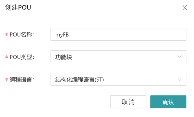
Create a POU by right-clicking on the application-> the POU, selecting the POU type as the function block, and selecting the programming language used. For example, the following diagram defines a function block named myFB and writes the function block in ST language.
It is not allowed to assign values to the output variables of a function block unless it is inside a function block. Assigning values to input variables for function blocks is only allowed as part of function block calls. The unassigned input of a function block should retain its initial value or the last called value, if any. The following table summarizes the allowed usage of the input and output variables for function blocks, and the examples are shown in ST language.
| Usage | Internal function block | External function block |
|---|---|---|
| Input read | IF IN1 THEN ... | Not allowed |
| Input assignment | Not allowed | FB_INST(IN1:=A,IN2:=B); |
| Output read | OUT := OUT AND NOT IN2; | C := FB_INST.OUT; |
| Output assignment | OUT := 1; | Not allowed |
| In-out read | IF INOUT THEN ... | IF FB1.INOUT THEN... |
| In-out assignment | INOUT := OUT OR IN1; | FB_INST(INOUT:=D); |
Global variables defined in GVL can be declared by VAR_EXTERNAL, and the variable values of global variables can be modified within the function block.
There is no need to define additional EN and ENO parameters in the function block definition, and the corresponding logic will be automatically generated by the system.
# 5.4.2.2 The Function Block Executes the Control Logic
In the function block definition, the system provides an additional Boolean EN (Enable) input or ENO (Enable Out) output, similar to the following definition:
VAR_INPUT EN: BOOL := 1; END_VAR
VAR_OUTPUT ENO: BOOL; END_VAR
When using these two variables, the execution of the operation of the function block will be controlled according to the following rules:
- When a function block instance is called, if the value of EN is FALSE(0), the operation defined in the function block logic will not be executed, and the ENO will be set to FALSE by the system.
- If the value of EN is TRUE(1), ENO will be set to TRUE by the system, and the logical operation in the function block logic body will be executed;
According to the above rules, the FALSE value entered by EN can be used to "freeze" the operation of the relevant function block; That is, the output value does not change regardless of any other input value changes. When the EN input value becomes TRUE, the function block can resume normal operation. Each time a function block with an EN input of FALSE is called, the ENO output value is FALSE. When EN is TRUE, the TRUE value of ENO reflects the normal execution of the function block.
# 5.4.2.3 Standard Library Function Blocks
Standard function blocks can be overloaded and can have extensible input and output.
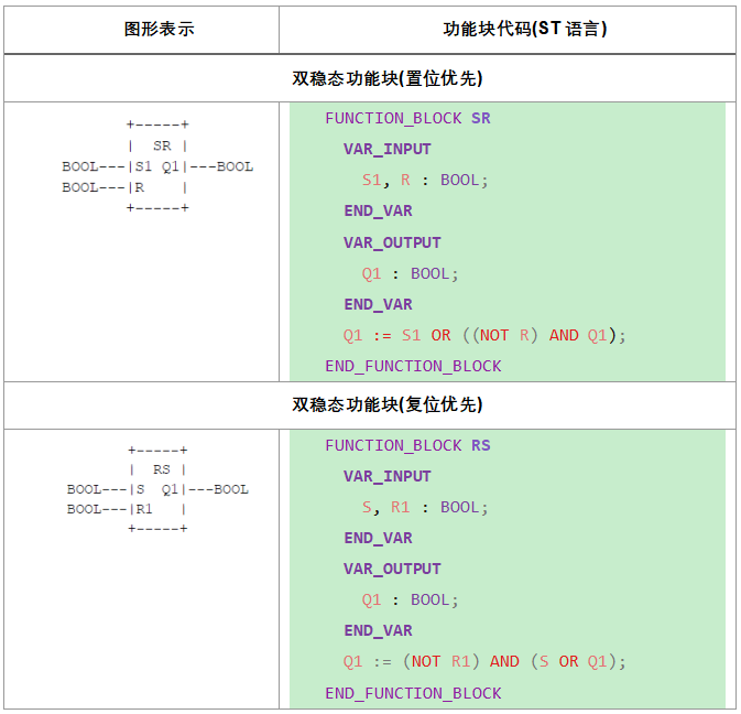
# 5.4.2.3.1 Bistable Elements
Bistable function blocks include set-priority function blocks (SR) and reset priority function blocks (RS).
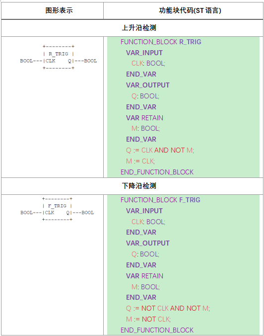
# 5.4.2.3.2 Edge Detection
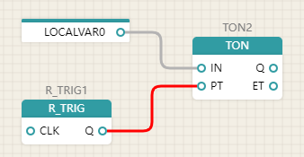
The behavior of the standard rising and falling edge detection function blocks corresponds to the following rules:
- After the Q output of the R_TRIG function block is converted from 0 to 1 in the CLK input, the value of BOOL#1 should be maintained from one execution of the function block to the next execution, and 0 should be returned on the next execution.
- After the Q output of the F_TRIG function block is converted from 1 to 0 in the CLK input, the Q value should remain at the BOOL#1 value and return 0 on the next execution from one execution to the next execution of the function block.
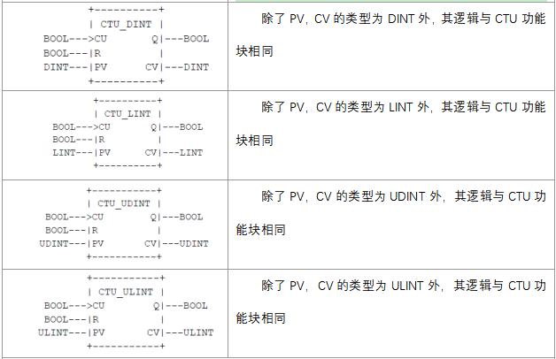
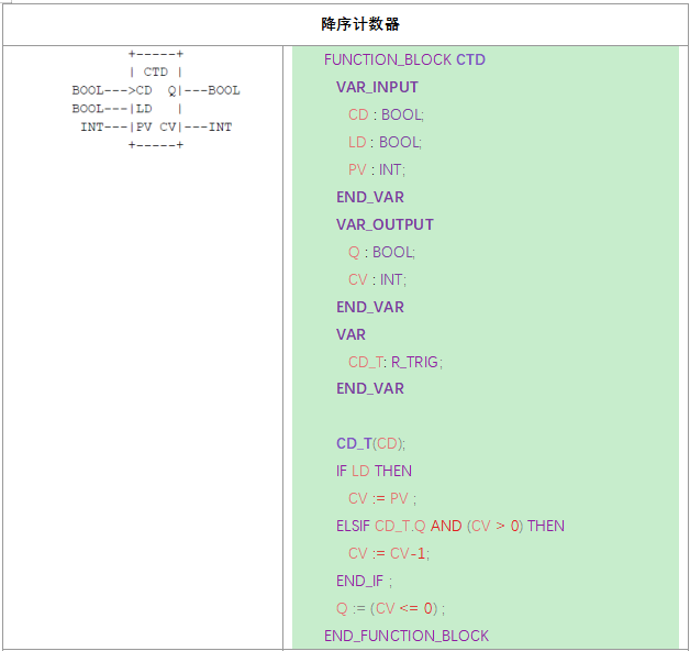
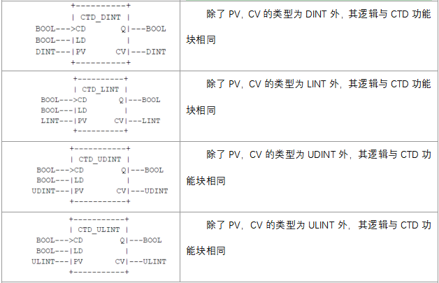
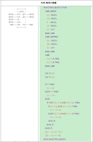
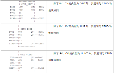
# 5.4.2.3.3 Counters

# 5.4.2.3.4 Timer
The graphical form of the standard timer function block is shown in the following table.
| Description | Graphic |
|---|---|
***It is expressed as:TP(Pulse Timer) TON (Power-On Delay Timer) TOF (Power-off Timer) |  |
The operation of these function blocks should be defined according to the sequence diagram shown in the following table.
| TP pulse timer |
|---|
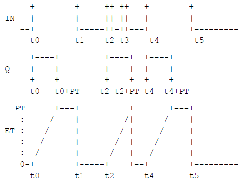 |
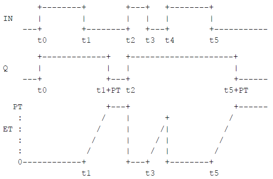
| Power-on Delay (TON) timer |
 |
| Power-off delay (TOF) timer |
 |
# 5.4.3 Procedure
The declaration and usage of a program is the same as that of a function block.
# 5.5 Configuration Elements
# 5.5.1 Configuration, Resources, and Access Paths
A configuration can be understood as a complete set of control systems for a set of equipment, and a configuration consists of one or more resources.
Resources are used to support the execution of tasks, and resources can contain multiple tasks, program organizational units, global variables, and so on.
Global variables are used to exchange data between program organizational units, and access paths provide an interface for external communication in the current configuration.
# 5.5.2 Tasks
A task is the scheduler of a program that is used to execute one or more programs. There are several types of tasks: loop, event, inertial coasting. Recurring tasks are performed at regular intervals; Event-based tasks start executing on the rising edge of the event variable. Tasks have different priorities, and tasks with higher priority can be interrupted by interrupting tasks with lower priority and preemptively executed.
# 5.6 Text Language
# 5.6.1 Textualization of Structure
Structured text (ST) is a high-level text language that can be used to describe the behavior of functions, function blocks, and programs. It consists of expressions and various statements.
# 5.6.1.1 Expressions
Expressions consist of operators and operands. The following table summarizes the operators for the ST language. The evaluation of the expression applies the operators to the operands in the order in which the operator precedence is defined as shown in the table. The operator with the highest priority in the expression should be evaluated first, followed by the operator with the second priority, and so on until the evaluation is complete. Operators with equal priority should be used in the order from left to right in the expression. For example, if A, B, C, and D are INT types with values of 1, 2, 3, and 4, respectively, then A+B-CABS(D) will be calculated as -9, and (A+B-C)*ABS(D) will be calculated as 0.
When an operator has two operands, the leftmost operand should be calculated first. For example, in the expression SIN(A)*COS(B), the value of SIN(A) will be evaluated first, followed by COS(B), and finally the result of the multiplication will be evaluated.
The following situations are considered syntax errors when performing an operation:
- The divisor is 0
- The operand is not the correct data type for that operation.
- The result of a numerical operation is outside the range of values for its data type.
Boolean expressions can only be evaluated within the range necessary to determine the resulting value. For example, in the expression (A>B) & (C<D), if the preceding condition (A>B) is FALSE, then it can be determined that the value of the entire expression (A>B) & (C<D) is FALSE, and the expression (C<D) is short-circuited and will not be evaluated.
A function should be called as an element of an expression, which consists of a list of arguments followed by parentheses by the function name.
# 5.6.1.2 Operators
| Operator | Sign | Priority |
|---|---|---|
| brackets"()" | (expression) | High |
| function call | Identifier (parameter list) | |
| negative | - NOT | |
| exponentiation | ** | |
| multiplication division summation | * / MOD | |
| addition subtraction | + - | |
| comparison | <,>,<=,>= | |
| equal to not equal to | = <> | |
| boolean and boolean and | & AND | |
| Boolean XOR | XOR | |
| Boolean or | OR | Low |
# 5.6.1.3 Statements
The following table lists the statement formats supported by the ST language, and each statement needs to end with a semicolon.
| Statement | Example |
|---|---|
| Assignment | A := B; CV := CV+1; C := SIN(X); |
| +=/-= | A += B; equal to A := A + B; |
| Function block invocation and function block output | CMD_TMR(IN:=%IX5, PT:=T#300ms) ; A := CMD_TMR.Q ; |
| RETURN | RETURN ; |
| IF | D := BB - 4AC ; IF D < 0.0 THEN NROOTS := 0 ; ELSIF D = 0.0 THEN NROOTS := 1 ; X1 := - B/(2.0A) ; ELSE NROOTS := 2 ; X1 := (- B + SQRT(D))/(2.0A) ; X2 := (- B - SQRT(D))/(2.0A) ; END_IF ; |
| CASE | TW := BCD_TO_INT(THUMBWHEEL); TW_ERROR := 0; CASE TW OF 1,5: DISPLAY := OVEN_TEMP; 2: DISPLAY := MOTOR_SPEED; 3: DISPLAY := GROSS - TARE; 4,6..10: DISPLAY := STATUS(TW - 4); ELSE DISPLAY := 0 ; TW_ERROR := 1; END_CASE; QW100 := INT_TO_BCD(DISPLAY); |
| FOR | J := 101 ; FOR I := 1 TO 100 BY 2 DO IF WORDS[I] = 'KEY' THEN J := I ; EXIT ; END_IF ; END_FOR ; |
| WHILE | J := 1;WHILE J <= 100 & WORDS[J] <> 'KEY' DO J := J+2 ; END_WHILE ; |
| REPEAT | J := -1 ; REPEAT J := J+2 ; UNTIL J = 101 OR WORDS[J] = 'KEY' END_REPEAT ; |
| EXIT | EXIT ; |
| Empty | ; |
Assignment statements
An assignment statement replaces the current value of a single or multiple element variables with the result of an expression evaluation. The assignment statement should contain a variable on the left, followed by the assignment operator ":=", and finally the expression that asks for the value. For example, the statement A:= B; If both are of type INT, the individual data value of variable A will be replaced with the current value of variable B. However, if both A and B are struct types, then the values of all elements of the structured variable A will be replaced by the current values of the corresponding elements of variable B.
Assignment statements can also be used to assign a function return value by placing the function name to the left of the ST statement assignment operator. The return value of the function should be the result of the last assignment. The function definition must contain at least one such assignment to determine the return value, otherwise the function will return the default value of the function return value type.
Functions and function blocks control statements
Function and function block control statements consist of calling functions or function block statements. Return control to the calling entity at the end of the function or function block.
Function evaluation should be used as part of expression evaluation; A function block invocation statement consists of a function block instance name followed by a list of parameters in parentheses.
A RETURN statement can exit a function, function block, or program in advance.
Select statement
The selection statement includes an IF statement and a CASE statement. A selection statement selects a block (or set) of statements that executes it based on the criteria specified. An example of a choice statement is given in the table above.
The IF statement specifies that a set of statements is executed only when the associated Boolean expression evaluates to 1 (TRUE). If the condition is false, no statement is executed, or the block of the statement after the ELSE keyword is executed (or the statement after the ELSIF keyword is executed, if the associated Boolean condition is true).
A CASE statement consists of an expression and a list of statement groups that evaluate to variables of type ANY_INT or enumerated data type, each of which is marked by one or more integers or enumerated values or integer ranges, as the case may be. It specifies the execution of the first set of statements, one of which contains the calculated value of the variable. If the value of the variable does not appear in the range of any CASE, the sequence of statements following the ELSE keyword is executed if it appears in the CASE statement. Otherwise, no statement sequence is executed.
Circular statements
A circular statement is a set of related statements that are to be executed repeatedly. If the number of loops can be determined in advance, it is recommended to use the FOR statement. Otherwise, you can use a WHILE or REPEAT loop statement.
The EXIT statement should be used to end the loop before the loop termination condition is met.
When the EXIT statement is in a nested loop construct, EXIT should terminate the innermost loop where EXIT is located, i.e., EXIT should be passed to the next statement after the first loop terminator (END_FOR, END_WHILE, or END_REPEAT) after the EXIT statement. For example, after executing the statement shown in the following image, if the value of the Boolean variable FLAG is 0, then the value of the variable SUM should be 15, and if FLAG=1, it should be 6.
| SUM := 0 ; FOR I := 1 TO 3 DO FOR J := 1 TO 2 DO IF FLAG THEN EXIT ; END_IF SUM := SUM + J ; END_FOR ; SUM := SUM + I ; END_FOR ; |
|---|
The FOR statement indicates that a sequence of statements should be executed repeatedly until the keyword is END_FOR, while assigning a series of values to the FOR loop control variable. The control variable, initial value, and final value must be expressions of the same integer type (for example, SINT, INT, or DINT) and cannot be changed by any repetitive statements. The FOR statement increments the control variable from the initial value up or down to the final value, and the increment is determined by the value of the expression; This value defaults to 1. The determination of the termination condition is made before the start of each loop, so if the initial value exceeds the final value, the statement sequence is not executed.
The WHILE statement will repeat the sequence of statements that preceded the END_WHILE keyword until the associated Boolean expression is FALSE. If the initial value of the expression is FALSE, this set of statements is not executed at all.
The REPEAT statement repeats the sequence of statements that preceded the END_REPEAT keyword until the associated Boolean expression is FALSE. If the initial value of the expression is FALSE, this set of statements will also be executed once.
# 5.7 Graphical Programming
# 5.7.1 Ladder Diagram (LD)/Function Block Diagram (FBD)
# 5.7.1.1 Connecting Cables
The connection line is used to connect the input and output ports of the graphic elements and control the execution logic of the PLC program. In the IEC61131-3 XML specification, the array of coordinates of the connection consists of [rear input port coordinates,..., front output port coordinates].
In the IDE, when the input and output types of the connection elements match, the connection line color is "gray". When the types do not match, the connection line is displayed in red.
When dragging an element from the right toolbox onto a port for an element in the canvas, the port is highlighted in purple, releasing the dragged element. When connecting an input port, a line is created by default that connects to the first output port of the dragged element. When connecting an output port, a connection to the first input port of the dragged element is created by default. When you drag and drop variable elements to automatically connect, the variable will automatically be converted into an input or output variable.

# 5.7.1.2 Designation
A designator name consists of an identifier that contains letters, numbers, or an unsigned decimal integer. The network is marked by the label, and the corresponding network label is used to execute the logical jump in the network. By default, a marker element is added to the coordinates of the upper left corner of the network, and the jump is executed from the starting position of the network.
When you drag and drop a grid in the IDE, the coordinates of the marker cannot be modified. You can modify the name of the label by clicking on it.

# 5.7.1.3 Segment (Network)
The net contains network labels, annotations, and graphic elements. By grouping the execution logic, a segment network is formed. Each segment of the network should have a unique designator. Compared with the FBD function block diagram, the LD ladder diagram should also have contacts, contacts, coils, and left and right power lines.
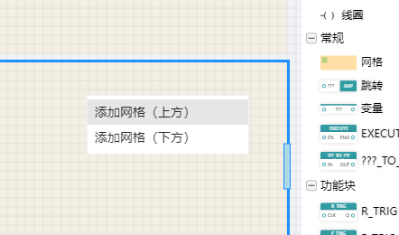
When you add an LD/FBD program to the IDE, a grid is added by default. Drag and drop a new grid from the right toolbox, or add a new grid above or below the current grid via the context menu on the selected grid.
# 5.7.1.4 Contacts
Contacts are used to read Boolean values from variables and are of four types:
- Normally Open Contacts: Right End = Left End AND Contact Variable
- Normally closed contact: right end = left end AND NOT contact variable
- Rising edge contact: if left AND "contact variable was FALSE in last cycle" AND "contact variable is TRUE in current cycle", right = TRUE; else: right = FALSE
- Falling edge contact: if left end AND "contact variable was TRUE in last cycle" AND "contact variable is FALSE in current cycle", right end = TRUE ; else: right end = FALSE
# 5.7.1.5 Coils
The coil is used to output Boolean values to writable variables, including 6 types
- Normal Coil: Writes a boolean value to the left end
- Nevert coil: Write the negation value at the left end
- Set coil: write TRUE when the left end is TRUE; When the left end is FALSE, the value of the previous period is maintained
- Reset coil: write FALSE when the left end is TRUE; When the left end is FALSE, the value of the previous period is maintained
- Rising edge coil:if left end AND "contact variable was FALSE in the previous cycle" AND "contact variable is TRUE in the current cycle": write TRUE; else: stay unchanged.
- Falling edge coil: if left end AND "contact variable was TRUE in the previous cycle" AND "contact variable is FALSE in the current cycle": write TRUE; else: stay unchanged
# 5.7.1.6 Left and Right Power Cords
The ladder diagram is very similar to the circuit diagram in the electrical control system, when analyzing the logical relationship of the ladder diagram, in order to borrow the analysis method of the relay circuit diagram, it can be imagined that there is a left positive and right negative DC power supply voltage between the left and right power lines, and there is energy flow between the power lines flowing from left to right, and the right bus can not be drawn.
# 5.7.1.7 Implementation Control(control flow)
When using functions based on LD graphics, you can use EN and ENO control execution. The function will only be executed if EN is TRUE; If the function is executed, the ENO output is TRUE by default, and if the execution process is abnormal, the ENO output is FALSE.
IEC61131-3 prohibits recursive calls, and does not allow the same type of POU to be called in a POU, which will make the PLC system unable to calculate the memory space required for runtime.
# 5.7.1.8 Use of Functions and Function Blocks
Functions have a return value type, and assigning a value to the function name at the time of declaration indicates that the return value is output, and it does not need to be instantiated when used, and can be used directly. Some mathematical operations such as ADD, MAX, etc., can adjust the number of input parameters.
When using a function block, you need to declare a local variable of this type as the instance name. When writing a user-defined function block, add input and output variables as the input and output of the function block.
By modifying the priority, you can adjust the order in which elements are executed.
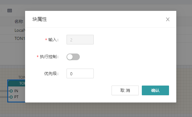
In the IDE, add the function blocks or functions that need to be used in the toolbox, and modify the properties by double-clicking on the element.
Adjust the number of input parameters for mathematical operations such as ADD and MAX by modifying the input attributes; By modifying the execution control, enable or disable the EN and ENO enable ports of functions and function blocks. Adjust the order in which elements are executed by modifying the priority.
# 5.7.1.9 Jump Execution
Bind the designator of the jump network to the jump symbol, and when the logic is executed, jump to the start of the network to start the execution.

# 5.8 C/CPP
# 5.8.1 POU Specification-2023 Written in C/CPP Language
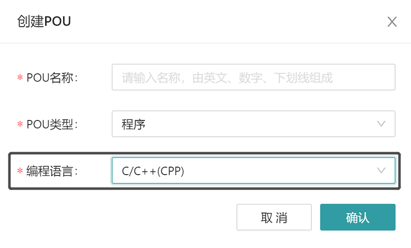
When creating a POU, select the C/C++ (CPP) option in the programming language options, as shown in the following figure, and then write the main code of the POU in C/CPP language. This is an extension of the five programming languages supported by the IEC61131-3 standard.
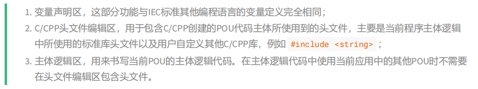
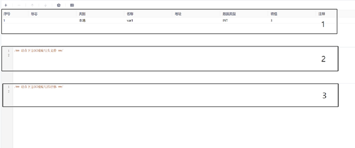
Open the POU you just created, as shown in the figure below, unlike POUs created in other IEC programming languages, POUs created in C/CPP programming languages have three editing areas. As shown in the figure below, they are:
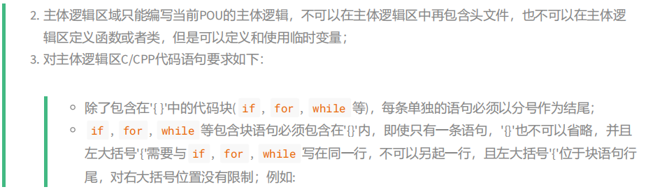
# 5.8.2 C/CPP Language POU General Specification
Create a POU in the C/CPP programming language as an extension to the IEC61131-3 standard. POU creators must comply with the following specifications:

# 5.8.3 Defining and Using Temporary Variables in the C/CPP Body Logical Area
C/CPP temporary variables are variables defined in the main logical area, which can be C/CPP data type variables (such as int , bool , or std::string) or IEC basic variable types (such as INT , BOOL), for example, in the logical body area there are the following definitions:
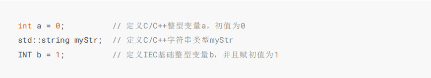
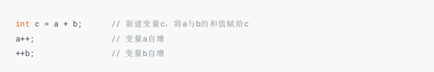
When using variables a and b, it is sufficient to meet the standard C/C++ specification, such as:
# 5.8.4 Use the Variables Defined in the Variable Definition Area in the C/CPP Body Logic Zone
The software provides functions such as writing variables, forcing variables, and monitoring variables. These variables need to be defined in the variable definition area. For ST/LD/FBD programming languages, they do not allow variables to be defined in the main logical area, so for ST/LD/FBD programming languages, all variables can be monitored, written, and enforced. However, the POU written in C/CPP allows temporary variables to be defined in the main logical area, but the variables defined in the main logical area cannot be monitored, written, and coerced, and the variables defined in the main logical area can only be temporary, which will be recreated and initialized every time the execution is completed, and the variable memory is released after the execution. It is recommended that programmers create POUs in C/CPP that are consistent with ST/LD/FBD and do not define IEC temporary variables in the main logic area.
The variables defined in the variable definition area can be divided into the following categories according to their types:
- IEC base type variables
- IEC enumeration type variables
- IEC array type variables
- IEC structure type variables
- IEC Function Block Type Variables
# 5.8.4.1 IEC Base Type Variables
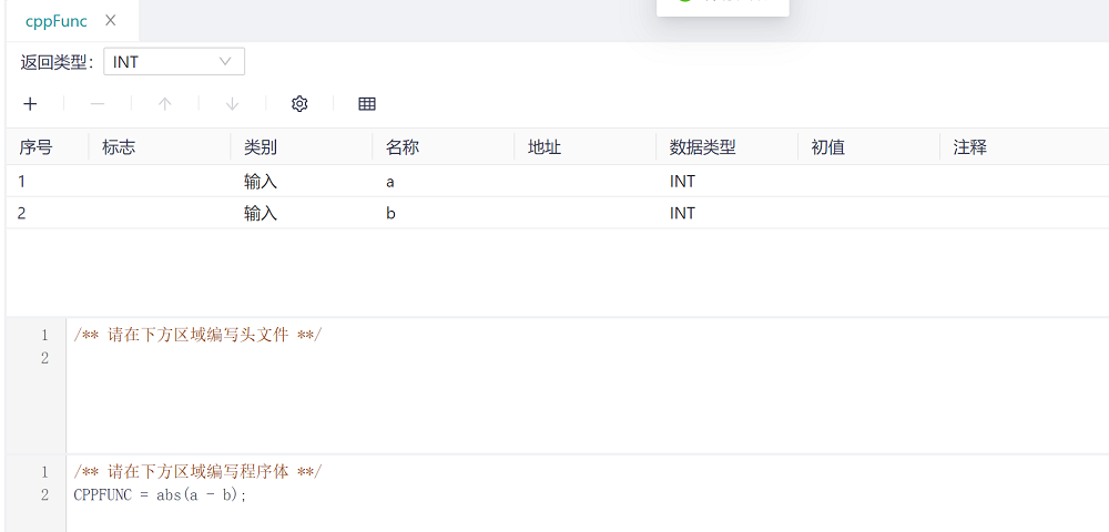
IEC base type variables refer to the variables declared in the variable declaration area, and the variable types are all IEC base data types (BOOL, SINT, etc.), except for the four time-related variables (TIME, TIME_OF_DAY, DATE and DATE_AND_TIME) and string (STRING) variables, the other basic types of variables operate the same as temporary variables. The only thing to note is that the POUs created by the C/CPP language are case-sensitive, for example, there is a : INT in the variable definition area; With such a definition, only variables such as a (note case) can be used as variable names in the main logical area. For example, we create a function called cppFunc, where there are two variables of type INT, a and b, and the function returns the absolute value of the difference between the two variables.

For more information about the function definitions in C/CPP language, see Function Definitions. Here is an example of how to use the variables of the IEC base type.
# 5.8.4.2 Time-dependent Data Types
There are four types of time-dependent data for IEC:
- TIME: Indicates a period of time
- TIME_OF_DAY:Indicates the time of day
- DATE:Indicates date
- DATE_AND_TIME: Indicates date and time
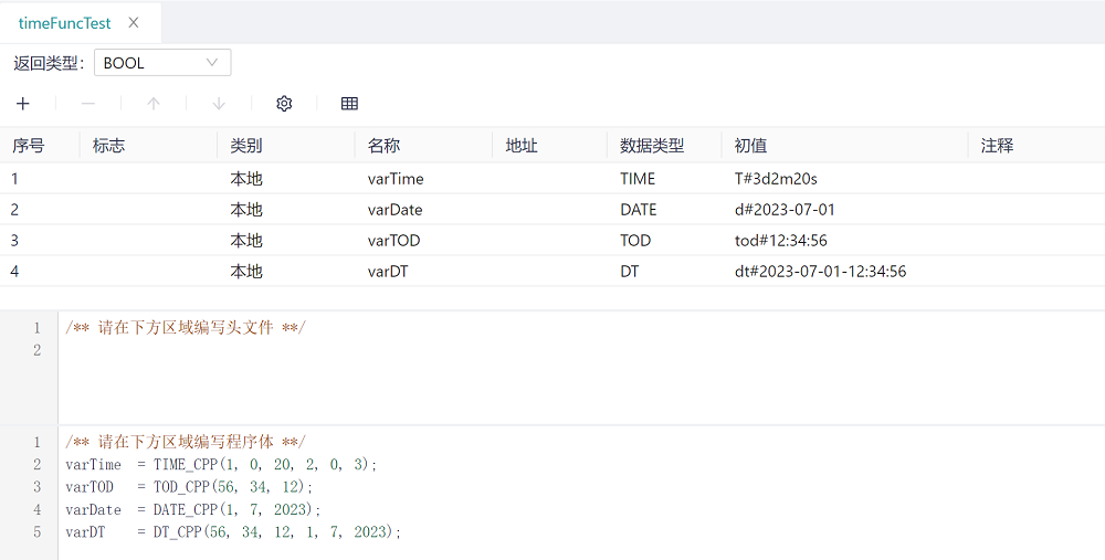
The assignment of time-related types is different from initialization, and the initialization of time-type variables in the variable definition area is consistent with the IEC standard, as shown in the figure below, the variable varTime of type TIME is defined, and the initial value is T#3d2m20s; However, to assign a variable value to the main logical area, you need to use TIME_CPP library functions, such as varTime = TIME_CPP(1, 0, 20, 2, 0, 3);
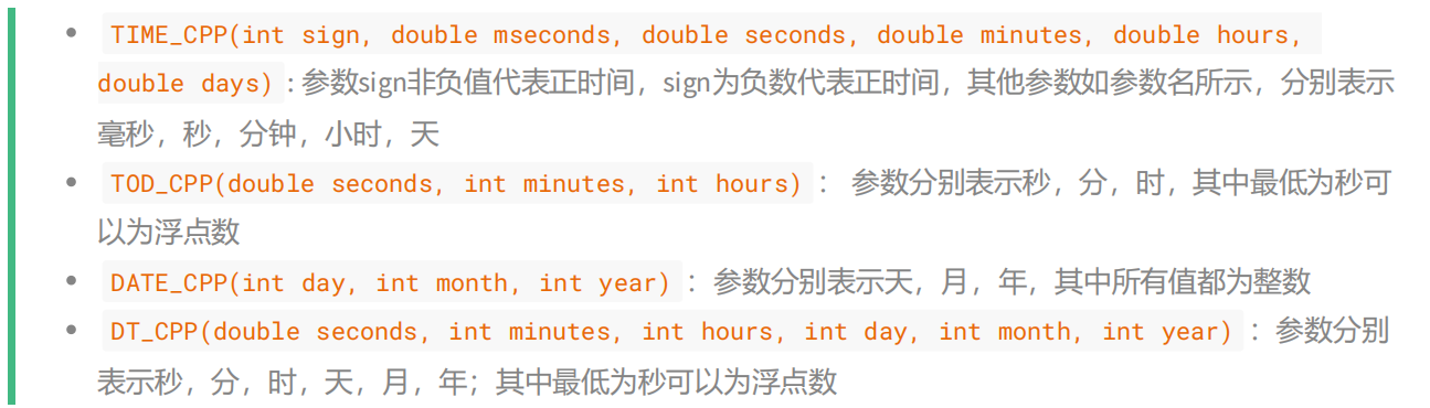
The following table describes the library functions of the time type:
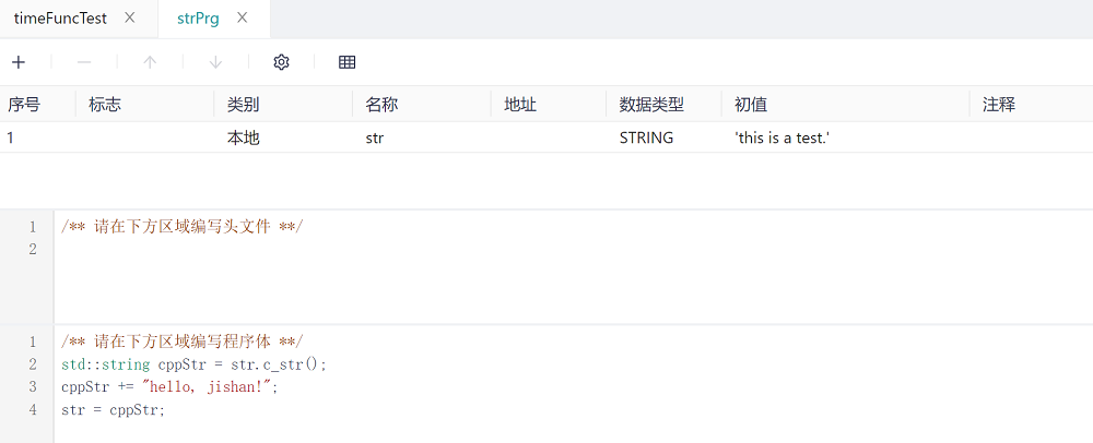
# 5.8.4.3 The String Type Variables
Different from initializing string types, initializing string types in the variable definition area is consistent with the IEC standard, and all string initial calues are inclosed in single quotes'. However, when using string literals in the C/CPP body logical area, double quotation marks are used, which needs to be noted here. Jishan provides two methods for variables of type string: c_str() and size(), which return a string of type C/CPP and the length of the returned string, respectively. For example, in the following example, first use the string cppStr of type std::string to get the value of str, and then concatenate the string cppStr with "hello, jishan!", and finally assign cppStr to str, where the value of the final str should be "this is a test. hello, jishan!"
# 5.8.4.4 IEC Enumeration Type Variables
For enumerated variables, initializing the enumerated variables in the variable definition area must conform to the ICE standard. The following structure is required to use the value of an enumerated variable in the main logical area:
Enumeration Type: Enumeration value
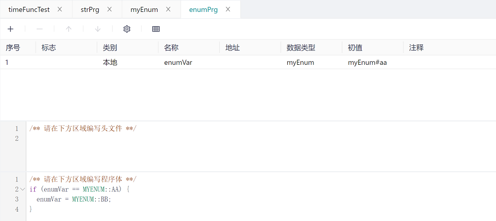
For example, if you have the following enumeration type myEnum definition, the enumeration has three values aa, bb, and cc.
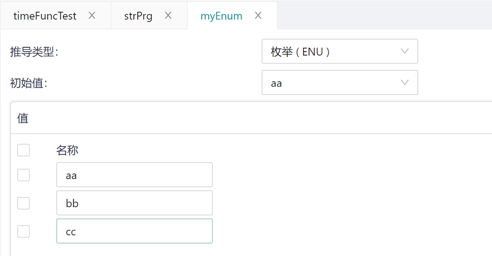
Then in the variable definition area and the main logic area, you need to use the enumeration type of variable values as follows. You can write myEnum#aa or AA directly when assigning the initial value to the variable definition area (again, the IEC standard is case-insensitive), but when using the enumeration type in the main logical area, you must use the MYENUM::AA form. Both the type and the value need to be capitalized.
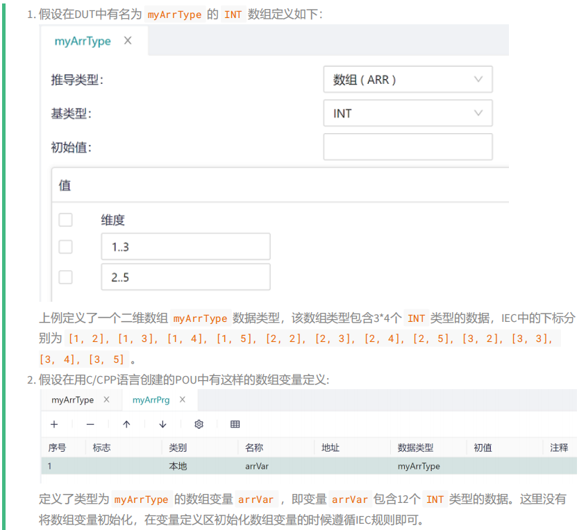
# 5.8.4.5 IEC Arry Type Variables
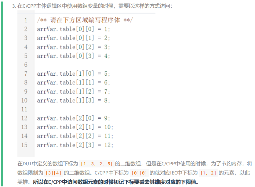
For array-type variables, the variables of the array type must be initialized in the variable definition area to comply with IEC standards, and the following structure needs to be used when using array-type variables in the main logical area:
array variables.table[1D subscript - dimension lower limit value][2D subscript - dimension lower limit value]...
For example:

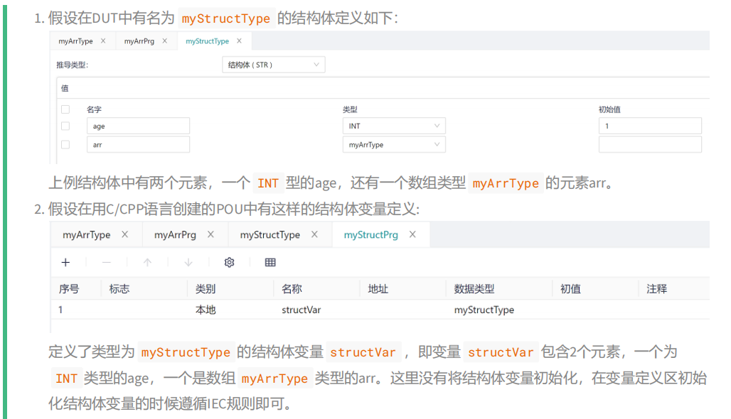
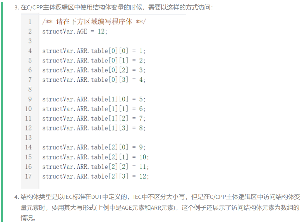
# 5.8.4.6 IEC Structure Type Variables
For structure variables, the variables that initialize the structure type in the variable definition area must comply with the IEC standard, and the following structures need to be used when using structure variables in the main logical area:

# 5.8.4.7 IEC Function Block Type Variables
For FB variables, the FB variables must be initialized in the variable definition area to comply with IEC standards, and the following structure must be used when using FB variables in the main logical area:
# 5.8.5 Creating and Using C/CPP Function Type POUs
- Create a function written in C/CPP
By right-clicking ->POU on the application of the Jishan IDE, the POU creation dialog box will pop up. As shown in the figure below:
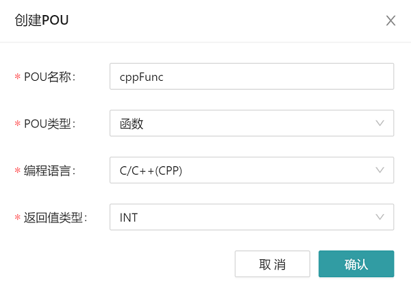
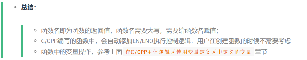
Enter the name of the function to be created (cppFunc) in the POU name, select the POU type as function, select C/CPP as the programming language, and select the return value type as needed. Click Confirm to create the function cppFunc, and the return value is INT, define the interface variables required by the function in the variable definition area, and write the logic of the function in the main logic area. It should be noted that, like other programming languages of IEC standards, in functions written in C/CPP language, the function name is the return value of the function, the function name needs to be assigned, and the function name belongs to the IEC element, so it needs to be capitalized.
For example, in the figure below, the function has two input parameters, named a and b, and this function returns the absolute value of the difference between the two input parameters.
- Functions are called in a POU written in C/CPP
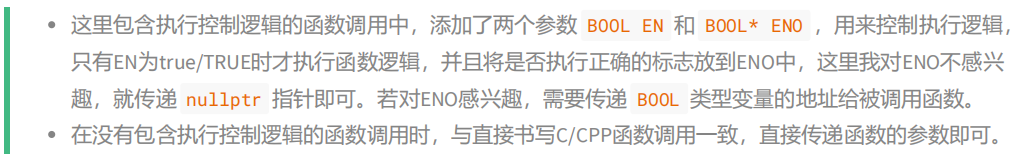
There are two ways to call a function in the body logic in C/CPP:

For example, if you call the functions created above in other POUs, you need to use the following two forms:
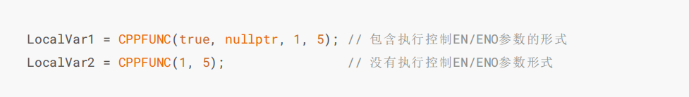
The premise is that in the variable definition area, the variables of type INT, LocalVar1 and LocalVar2, are defined in advance;
In the example given here, the function is created with only input variables. When a function is created, when a function is created, the output variables (parameters) of the function need to be passed to the called function by passing an address.
# 5.8.6 Create a POU With the C/CPP Function Block Type
- Create function blocks written in C/CPP
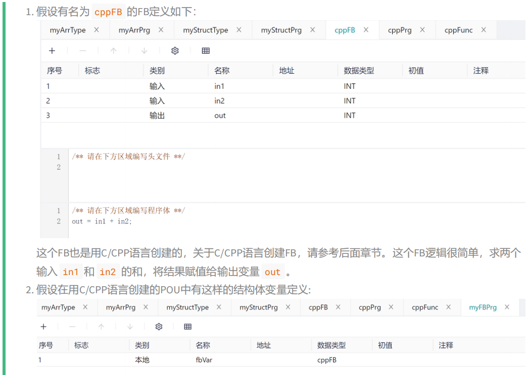
If you want to create a function block in C/CPP, you can create a function block by selecting the POU type as Function Block and entering the name of the function block in the POU Name dialog box. In the following example, the function block cppFB is created, as follows:
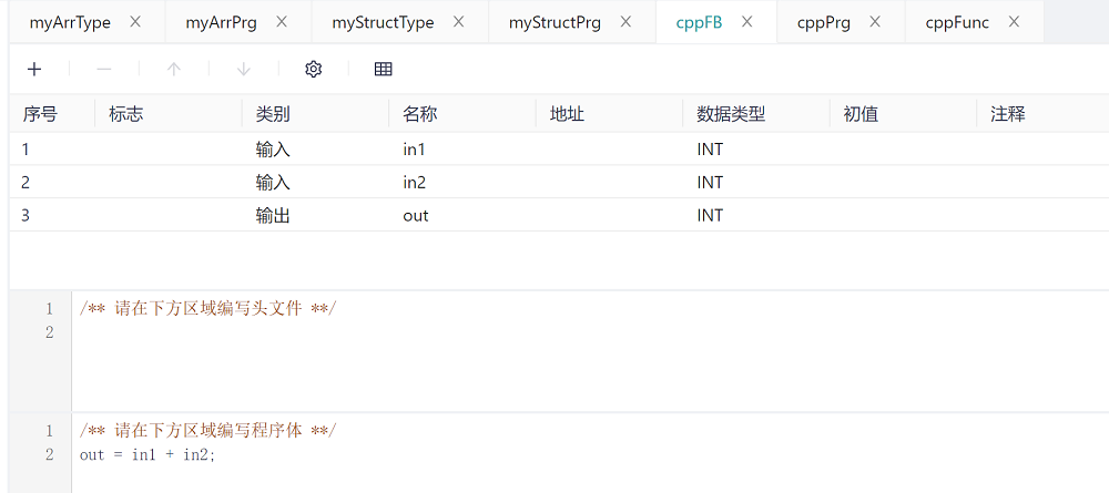
In the above example, the function block has two input parameters in1 and in2, and one output parameter out, and the function of the function block is to assign the sum of the two inputs to the output.
- Use function blocks in POUs written in C/CPP
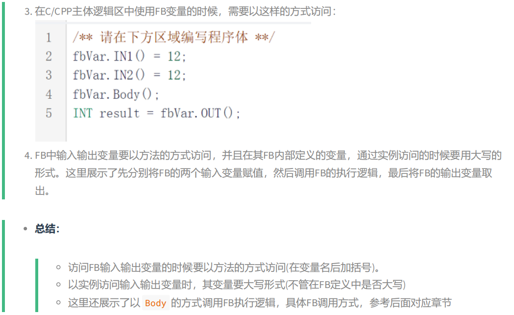
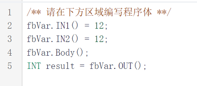
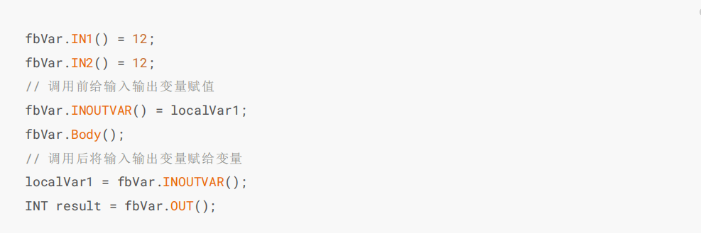
When using a function block in a POU written in C/CPP, you first need to define the variables of the function block type. When calling the function block logic, you need to first assign the input variables of the function block, then call the Body() method of the function block, and finally use the output variables of the function block. This is shown in the section "Variables for IEC function block types".
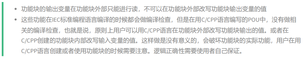
Only the input, output, and input/output variables of a function block can be accessed outside the function block.
If the function block contains input and output variables, when using it, you need to assign the input and output variables first, then call the function block logic, and finally assign the input and output variables to the current variable to implement the input and output logic. For example, if there is an INT input/output variable inouVar in the function block cppFB, then it needs to be called in the following way.
Note: The operation permissions of the variables of the function block are as follows:
| Usage | Function block internal | Function block external |
|---|---|---|
| INPUT variable read | allowed | not allowed |
| INPUT variable write | not allowed | allowed |
| OUTPUT varialbe read | allowed | allowed |
| OUTPUT variable write | allowed | not allowed |
| INOUT variable read | allowed | allowed |
| INOUT variable write | allowed | allowed |

# 5.8.7 Creating and Using of C/CPP Program Type POUs
When creating a program in C/CPP, the only difference is that the POU type is changed to the program.
The use of programs can only instantiate programs in a task, and we do not allow programs to call each other for the time being.
# 5.9 Sequential Function Chart Language (SFC)
The Sequential Function Chart (SFC) is defined in the IEC 61131-3 standard as a common element of the programming language. It is a programming method that describes the processes, functions and characteristics of a sequential control system using a combination of textual descriptions and graphical symbols. It can be used as either a text-based or a graphical programming language, but it is usually categorized as a graphical programming language. Thus, IEC 61131-3 is commonly referred to as having three graphical programming languages.
The SFC editor is shown below
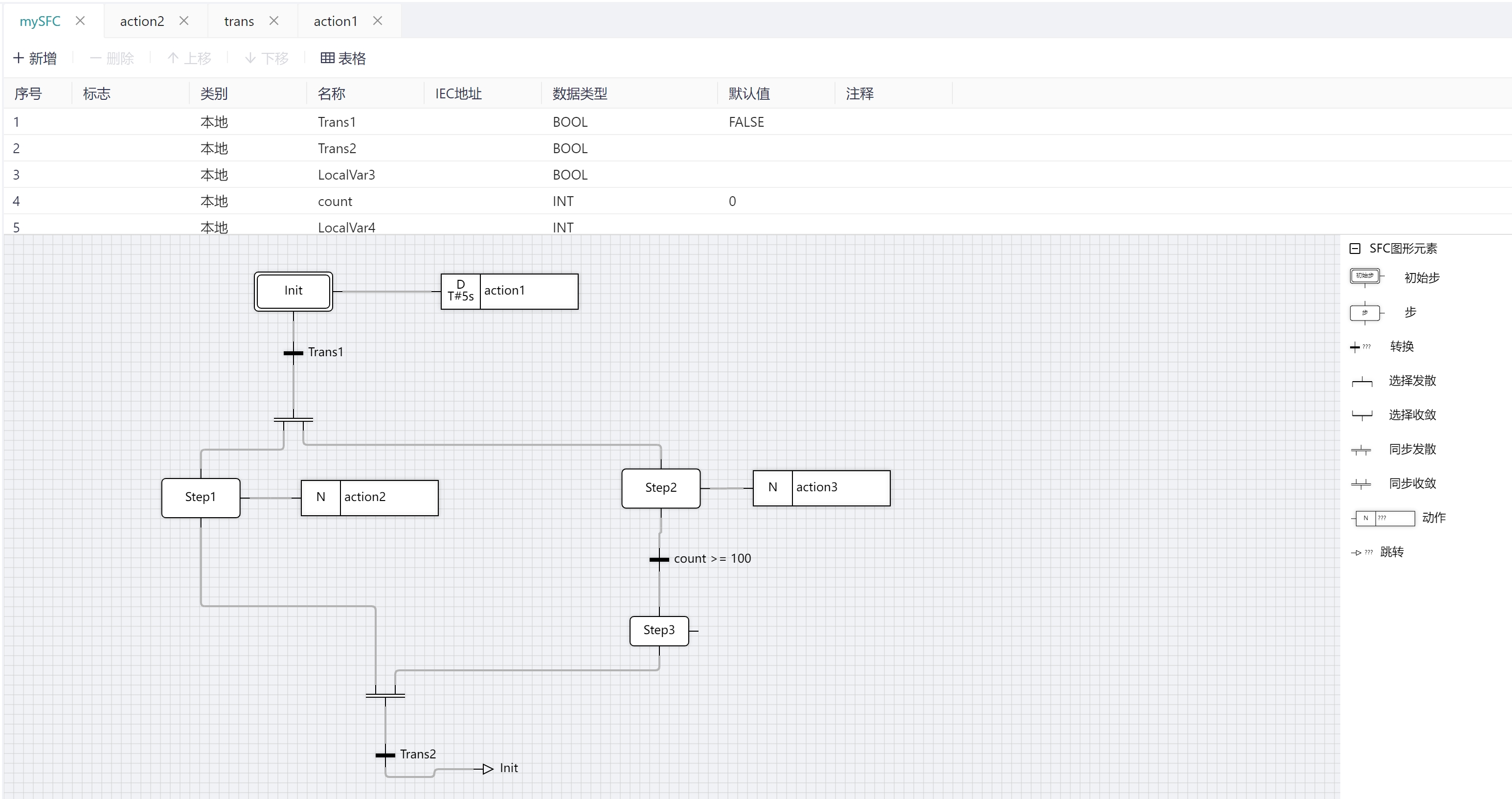 The SFC element provides a means of dividing a programmable controller program organization unit (POU) into a set of steps and transitions interconnected by directional lines. Associated with each step is a set of actions and associated with each transition is a transition condition.
Since SFC elements are required to store state information, the only program organizational units that can be constructed using these elements are function blocks and procedures.
# 5.9.1 SFC Components
The components of SFC include step, transition, action block, jump, divergent branch, and convergent branch.
The shape of each element of the SFC and its characteristics are shown in the table below.
| col1 | col2 |
|---|---|
| Step |  Initial step  Step |
| Transition |  |
| Action Block |  |
| Jump |  |
| Divergent branch |  Selective divergence  Synchronous divergence |
| Convergent branch |  Selective convergence  Synchronous convergence |
# 5.9.2 Step
Step represents a major function in an overall industrial process. It can be a specific time, a phase or an action performed by several devices. The input and output behavior of the program organization unit follows the execution action determined by the associated execution of the step. Step has only two states: active and inactive. At any moment, the state of the POU is defined by the set of active steps and the values of their internal and output variables.
Initial step
Each SFC language POU starts with an initial step, and the POU run always evolves from the initial step downwards. The initial step is an indispensable component of the SFC language POU and cannot be deleted.
The initial step is shown below.

Step
SFC POU supports the configuration of multiple common steps, which can be added and deleted, and each common step can be added with an entry action, an exit action, an associated step action, and an associated project management tree action.
The common step is shown below.

Activation step
When a step is active, online you can see the color of the step's border change to red and the action associated with the current step is called for execution.
As shown below.
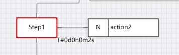
Activation step start time as step name.T(TIME):The current start time acquired by the step when the step was first activated.
Activate step runtime as step name.T(TIME): When the step has just been activated, the step gets the current start time(step name.T). And the running time of the step starts to accumulate, and the running time of the step is reset to T#0s when it runs until the step is de-activated.As shown above, step1 is active and ran T#2s, then Step1.T:=T#2s.
The next state of the step is the step name.X(BOOL): step activity flag, when the value is TRUE, it indicates that the next scheduling cycle of the step is active, when the value is FALSE, it indicates that the next scheduling cycle of the step is inactive.
The current state of the step is step name.X(BOOL): step activity flag, when the value is TRUE, it indicates that the current scheduling cycle of the step is active, and when the value is FALSE, it indicates that the current scheduling cycle of the step is inactive, as shown in the above figure Step1.X:=TRUE.
Step name, step runtime, and step status are only valid in the current POU and cannot be referenced in other POUs.
Step name constraint rules:
- the step name must satisfy the definition rules for variable names
- the step name cannot be the same as the variable name in this SFC POU variable area.
- the step name must not be a duplicate of the action.
# 5.9.3 Transition
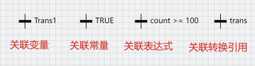
There are so-called conversions between steps. The value of the conversion condition must be a BOOL value (TRUE or FALSE). Thus, it can be a BOOL variable, a BOOL address, or a BOOL constant. A step conversion is performed only if the step's conversion condition is TRUE.
The individual transfer conditions are shown below.
Transfer constraint rules:
- If the conversion is associated with a reference POU, the variable area defined by the SFC conversion reference POU cannot define a variable with the transferred name.
- If the conversion is already associated with a POU, the SFC POU cannot add an action with the same transfer name to the project management tree.
- If the SFC POU adds an action with the same conversion name to the project management tree, the conversion cannot be associated with a POU, and the SFC POU cannot define a variable with the same conversion name.
- If multiple conversions have the same name (case insensitive), the same POU is associated with the conversion.
# 5.9.4 Action Block
The action block consists of a qualifier and an action name, the qualifier includes a time limiter and a non-time limiter, the qualifier determines the execution mode of the action associated with this action name, and the action associated with the action name is the action added to the SFC POU tree.
The action block is shown below.
The SFC qualifiers are shown in the following table:
| Qualifiers | Meaning | Description | |
|---|---|---|---|
| - | Non-stored (null qualifier) | Activate as long as the step activates the action, deactivate if the step deactivates | |
| N | Non-stored | Activate as long as the step activates the action, deactivate as long as the step deactivates the action | |
| R | Overriding Reset | Reset as long as the step is active, the step disabled state remains until the next activation | |
| S | Set (Stored) | Set as long as the step is active, the step failed state is held until the next activation | |
| L | Time Limited | The action is initiated when the step is active, and the action will continue until the step is inactive or the set time has expired | |
| D | time Delayed | The delayer starts after activation. If the step is still active after the delay, the action starts until the step is deactivated | |
| P | Pulse | When the step is activated for the first time, only one cycle is executed and then it is turned off | |
| SD | Stored and time Delayed | After the delay the action starts and it will continue to hold until restarted | |
| DS | Delayed and Stored | If the step is still active after the specified event delay, the action starts and continues to hold until restarted | |
| SL | Stored and time Limited | The action starts after the step is activated and continues for a certain amount of time or restarts | |
| P1 | Pulse (rising edge) | Execute on entry step and only once | |
| P0 | Pulse (falling edge) | Execute at exit step and only once |
NOTE: The qualifiers L, D, SD, DS, and SL shall have an associated duration of type TIME.
The action is named Project Management Tree the action hanging underneath this SFC POU, as shown below.
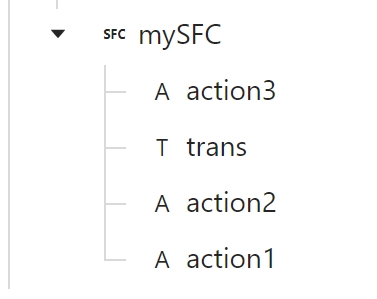
The SFC POU downstream action can be realized by the following steps
- Right click on the POU in SFC language.
- Select [Add Action] from the pop-up right-click menu.
- The Add Action dialog box will pop up.
- Name the action and click [OK].
The action supports ST, FBD, LD, SFC, and CPP languages.
# 5.9.5 Jump
Jump is actually an operation that connects to a step with a jump symbol or to a parallel branch with a label, and can be used to make the SFC cyclic by means of this component; the POU edited in the SFC language contains at least one jump. Jump is a program execution that can unconditionally go to the label associated with the jump for execution, and can transfer directly from a step to another step inside or outside the current branch or to a parallel branch with a label. Jump is used in place of a step and is executed by the transfer at its location; Jump is executed when the transfer condition is satisfied.
The jump element is shown below.
# 5.9.6 Divergent Branch
SFC divergence branch synchronized divergence branch and selective divergence branch.
Selective divergent branch
When the action output A of step n is executed, the step (n+1 or n+2) in which the first of the conversion conditions b or c is established is selected, and the action of the changed step is executed. When both conversion conditions are established, the left conversion condition takes priority and step n is invalidated. After conversion, each step of the selected column is executed in turn until the merged position is reached.
Synchronous divergent branch
When the action output A of step n is executed, step n+1 and step n+3 are activated at the same time if the transition condition b is valid, and step n is deactivated. Activate step n+2 when conversion condition c is valid, and activate step n+4 when conversion condition d is valid.
# 5.9.7 Convergent Branch
SFC Convergence Branch Parallels Convergence Branch and Selective Convergence Branch.
Selective Convergence Branch
If the transition condition b or c holds for the execution column in the branch, then invalidate execution step n or n+1 and activate step n+2.
synchronous convergence branch
When the action output A of step n and the action output B of step n+1 are executed, if the transition condition b and the transition condition c both hold, the wait step is activated and step n and step n+1 are invalidated. A wait step is a step used to synchronize the steps of parallel processing by converting all the steps of parallel processing to a wait step, checking the conversion condition d, and activating step n+2 if the conversion condition d holds. The wait step is treated as a virtual step, so it doesn't matter if no action is output.
# 5.9.8 Rules for The Evolution of Step
Step progression in the SFC programming language is related to the execution of actions and the realization of transformations. The rules for step evolution (progression) are as follows:
- The initial state is determined by the initialization of the program or function block containing the network at the initial step of the active state.
- The transition is an enabling transition when all preceding steps of that state are active steps. The transition occurs only when the transition condition of the is-enabled transition is
TRUE, thus enabling step evolution- Realization of a transition that makes inactive the predecessor step connected to the transition and makes active all subsequent steps connected to the transition
- Sequences in which multiple steps are made active at the same time are called synchronization sequences. Each of their summations is independent, and for this reason it is common to use horizontal lines to represent branches and mergers of synchronized sequences.
- Step/transition and transition/step shall always be maintained in the SFC element connection, i.e.:
- Two steps can never be directly connected; they are always separated by a transformation.
- Two conversions can never be directly connected; they are always separated by steps.
- The evolution of steps begins with the initial step. Therefore, the initial step should be the active step at the beginning of program execution.
- The action control function block connected to the step is executed only at the active step of the step, and the execution of the actions is determined according to the output Q of the action control block; when Q is TRUE, these actions are executed; when Q is FALSE, these actions are not executed.
- During the execution of an action, subsequent conversions are evaluated, and when the conversion conditions are met, the realization of the conversion occurs and the evolution of the step is realized, so that the step evolves according to the SFC program.
- Selecting a branch of the sequence, there are multiple conversion conditions, and they are prioritized. When no priority is set, the conversion conditions are judged from left to right. When the priority is set, the number indicates the priority, and the smaller the data, the higher the priority.
- Step activation takes some time, likewise the realization of the conversion takes some time. The time required varies from PLC product to PLC product. Therefore, when the action connected to the active step is limited to the delay function, the process of realizing the conversion may occur when the active step is about to activate the action, and thus the phenomenon that there is still an action being executed in the inactive step should be considered in the design.