# 7. Live Protocol Stack
# 7.1 Modbus TCP
# 7.1.1 Modbus TCP Master
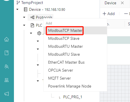
- Add a protocol stack
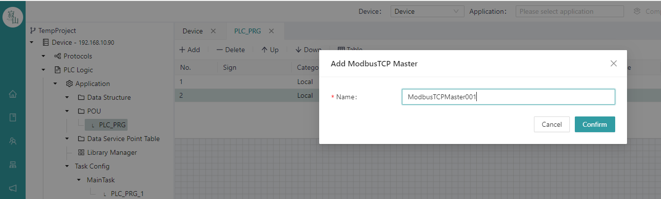
Right-click the "Communication Protocol Stack" node in the project tree, select "Modbus TCP Master" from the communication protocol stack list, modify the name of the protocol stack in the pop-up window, and click the "Confirm" button to view the newly added Modbus TCP Master protocol sub-node under the "Communication Protocol Stack" node in the project tree.
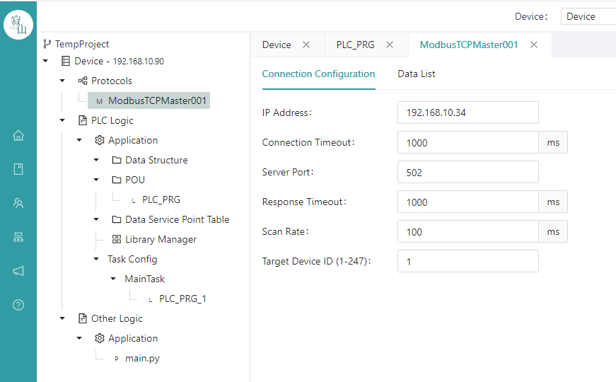
 Click the newly added protocol subnode to configure connection configuration and data operation on the protocol configuration page on the right side of the page.
- Configure communication parameters
The communication parameters of Modbus TCP Master include the IP address, port number, connection timeout, response timeout, and task interval of the slave device. The IP address is the IP address of the target slave, and the slave should be in the same network segment as the master. Server Port is the Modbus TCP slave service port of the target slave.
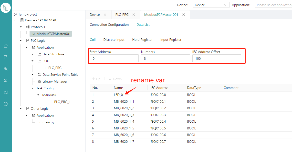
- Data manipulation configuration
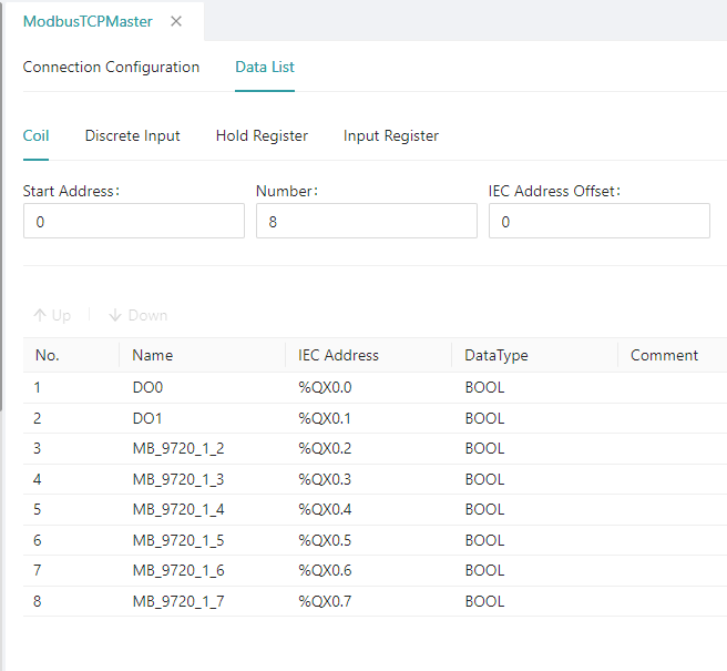
On the data operation page, the "Coil", "Discrete Input", "Hold Register", and "Input Register" can be configured according to the specific situation of the slave device. After the three parameters of "Start Address", "Quantity" and "IEC Address Offset" are filled, a corresponding number of points will be automatically generated at the bottom of the current page, and each point has a unique name, IEC address and data type, where the name of the point can be renamed, and these data points exist in the form of global variables, which can be used in the form of external variables in the user's POU program.
Instructions:
"IEC Address Offset" is used to automatically generate the IEC addresses of the point table, and users need to plan the addresses before configuration to ensure that the addresses do not overlap.
The "Start Address" starts from 0 by default and generally does not need to be modified;
It should be remembered that the sum of "Start Address" and "Quantity" should not exceed the number of actual slave coils/registers, i.e. should be a subset of the actual slave coils/registers; For example, if a slave device has 8 coils, 8 discrete inputs, 4 hold registers, and 4 input registers, their starting addresses and quantities can be set as:
| Type | Start address | Quantity | Instruction |
|---|---|---|---|
| Coil | 0 | 8 | 0+8<=8 |
| Discrete input | 0 | 4 | 0+4<=8 |
| Hold registers | 0 | 2 | 0+2<=4 |
| Input registers | 0 | 2 | 0+2<=4 |
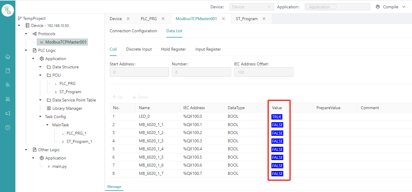
- View online variable real-time value
After the stack is configured, users can use the variables automatically generated by the stack in the POU. After writing a logical program, you can observe the running status of the stack on the interface after compiling, connecting, downloading, and running, and the real-time values of all variables are displayed in the column where the value is located.
- Delete the stack
In the offline state, right-click the Modbus TCP Master sub-node in the project tree and select Delete. Note that once the deletion protocol is executed, it cannot be recovered.
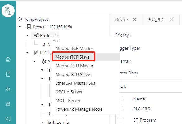
# 7.1.2 Modbus TCP Slave
- Add a protocol stack
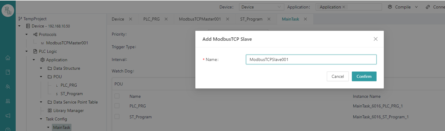
Right-click the "Communication Protocol Stack" node in the project tree, select "Modbus TCP Slave" in the communication protocol stack list, modify the name of the protocol stack in the pop-up window, and click the "Confirm" button to view the newly added Modbus TCP Slave protocol sub-node under the "Communication Protocol Stack" node in the project tree.
Click the newly added protocol subnode to configure connection configuration and data operation on the protocol configuration page on the right side of the page.
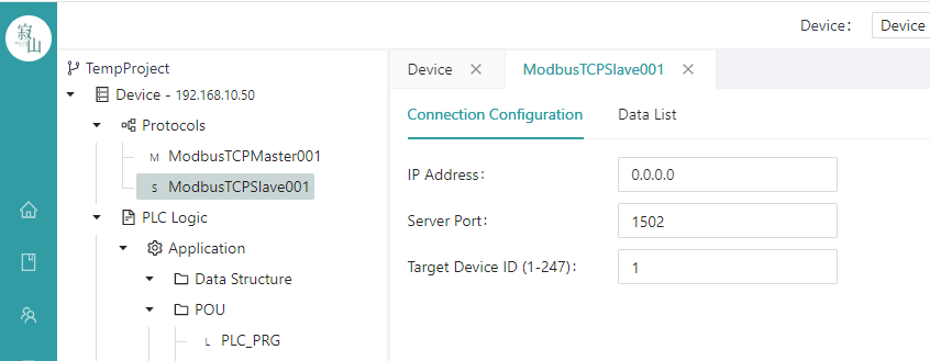
- Configure communication parameters
The communication parameters of the Modbus TCP Slave include the IP address and port number of the slave device, where IP Address is the IP address of the host network interface, which is 0.0.0.0 by default.0~65535 users should avoid using recognised port numbers for system services to prevent conflicts. That is, avoid using port numbers between 0 and 1023.
- Create a data table
The data table operation page can create four point tables, namely "Coil", "Discrete Input", "Holding Register" and "Input Register". "The starting address of each table starts from 0, and the number of tables can be decided according to the user's needs.
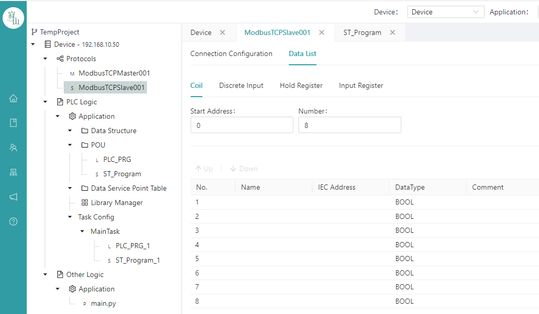
After the "Start Address" and "Quantity" parameters are configured, a point table of the corresponding number of points is automatically generated below, and then the user can bind the IEC variables with addresses in the application to the points in the table one by one; Click the blank space of the "name" of each row to select the existing IEC variables in the project to bind to the row, the available variables have been filtered according to the data type, and the variables that do not match the data type or do not have the IEC address will not be displayed; Rows that are not bound to variables default to 0 for all data.
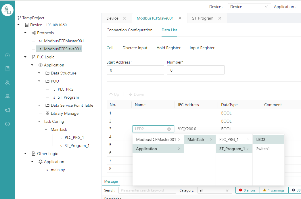
After bouding the variable, click the Save button or CTRL+S key to save.
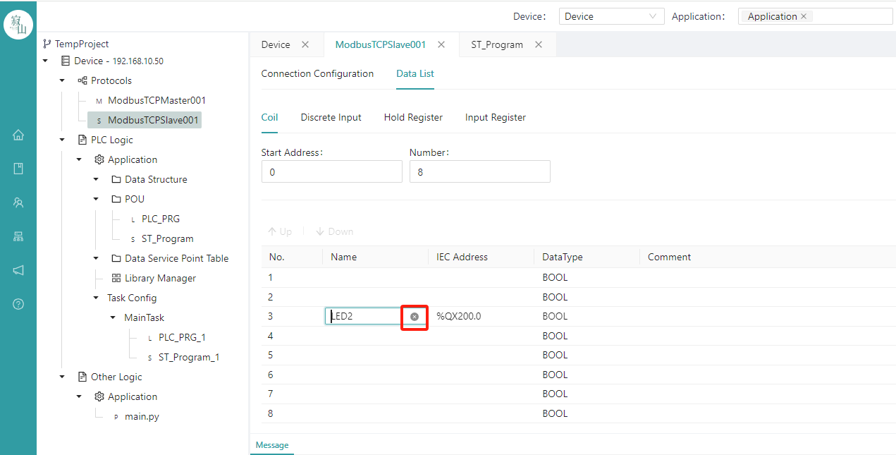
To pre-delete a bound variable, click the icon behind the cariable name to delete it.
- Status viewing
After the stack is configured, write a logic program in the POU, and observe the running status of the stack on the interface after the compile, download, and run steps.

- Delete the stack
In the offline state, right-click the Modbus TCP Slave sub-node in the project tree and select Delete. Note that once the deletion protocol is executed, it cannot undo.
# 7.2 Modbus RTU
# 7.2.1 Modbus RTU Master
- Add a protocol stack
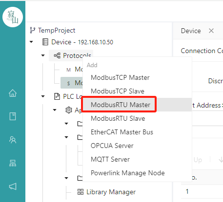
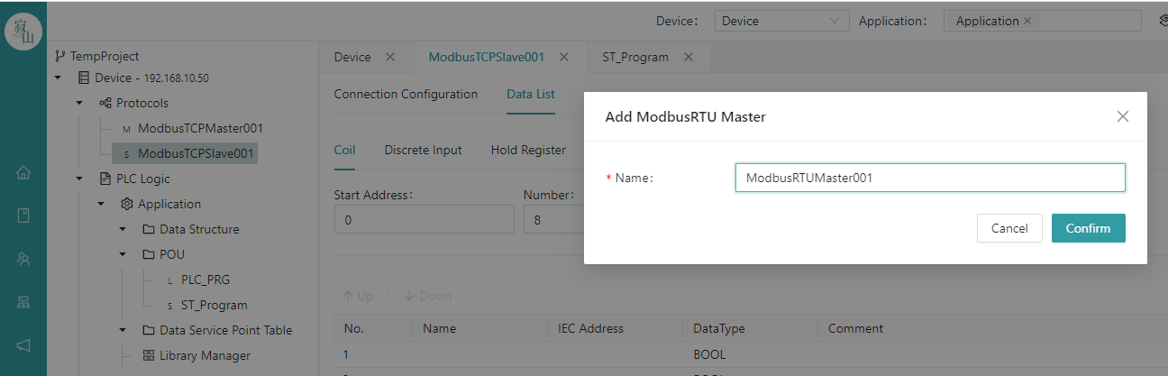
Right-click the "Communication Protocol Stack" node in the project tree, select "Modbus RTU Master" in the communication protocol stack list, modify the name of the protocol stack in the pop-up window, and click the "Confirm" button to view the newly added Modbus RTU Master protocol sub-node under the "Communication Protocol Stack" node in the project tree.
Click the newly added protocol subnode to configure connection configuration and data operation on the protocol configuration page on the right side of the page.
- Configure communication parameters
The communication parameters of the Modbus RTU Master include the COM port name of the slave, baud rate, parity bits, data bits, stop bits, response time, slave ID, and task interval.
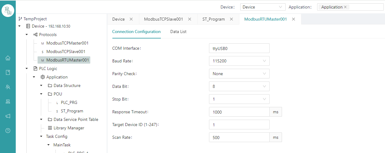
Commonly used communication parameter configuration:
COM port:ttyS0/ttyUSB0/… (Should match the name of master serial port device)
Baud rate:9600 or 115200 (Should match the ID of the slave device to be communicated with)
Parity heck:None (Should match the ID of the slave device to be communicated with)
Data bits:8 (Should match the ID of the slave device to be communicated with)
Stop position:1 (Should match the ID of the slave device to be communicated with)
Response timeout:1000ms
Slave ID:1~247 (Should match the ID of the slave device to be communicated with)
Task interval:generally not less than 100 ms
- Data manipulation configuration
Same as Modbus TCP Master, refer to Chapter 7.1.1.
- Real-time value view of online variables
Same as Modbus TCP Master, refer to Chapter 7.1.1.
- Delete the stack
Same as Modbus TCP Master, refer to Chapter 7.1.1.
# 7.2.2 Modbus RTU Slave
- Add a protocol stack
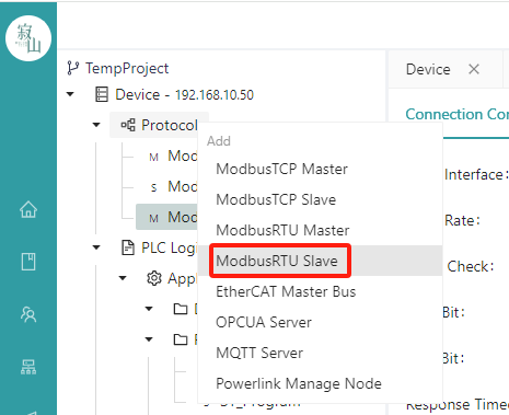
Right-click the "Communication Protocol Stack" node in the project tree, select "Modbus RTU Slave" in the communication protocol stack list, modify the name of the protocol stack in the pop-up window, and click the "Confirm" button to view the newly added Modbus RTU Slave protocol sub-node under the "Communication Protocol Stack" node in the project tree.
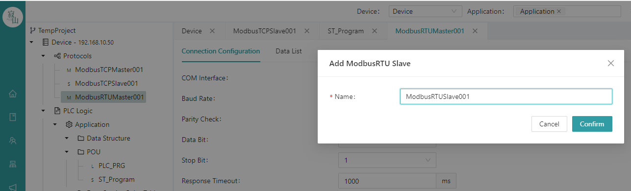
Click the newly added protocol subnode to configure connection configuration and data operation on the protocol configuration page on the right side of the page.
- Configure communication parameters
The communication parameters of the Modbus RTU Slave include the COM port name, baud rate, parity bit, data bit, stop bit, and local device ID of the master device.
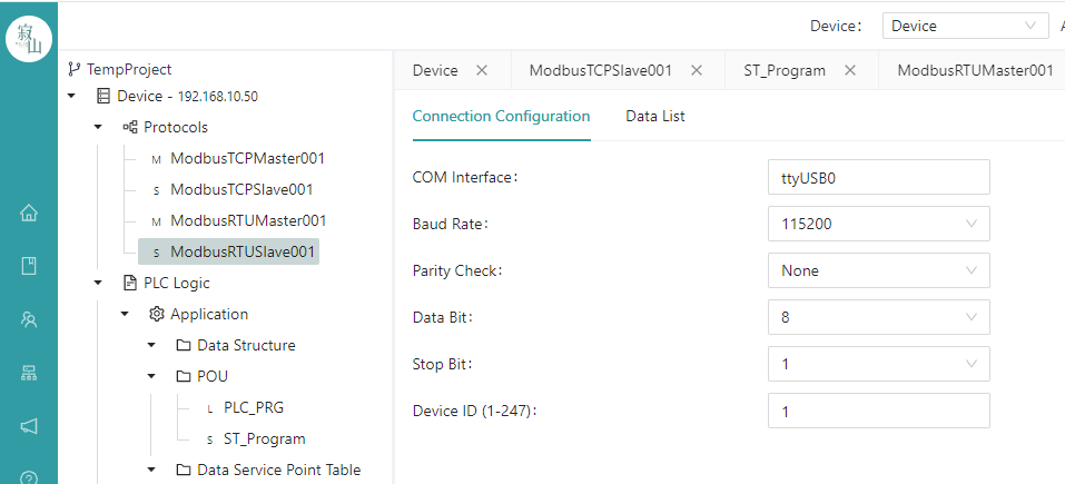
Commonly used communication parameter configuration:
COM port:ttyS0/ttyUSB0/… (should match the name of master serial port device)
Baud rate:9600 or 115200
Parity check:None
Data bits:8
Stop position:1
Device ID:1~247 (External Modbus RTU Master can address the current master with this ID)
- Create a data table
Same as Modbus TCP Slave, refer to Chapter 7.1.2.
- Unbind
Same as Modbus TCP Slave, refer to Chapter 7.1.2.
- Status viewing
Same as Modbus TCP Slave, refer to Chapter 7.1.2.
- Delete the stack
Same as Modbus TCP Slave, refer to Chapter 7.1.2.
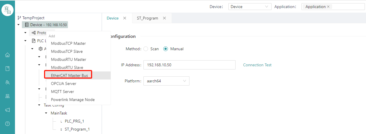
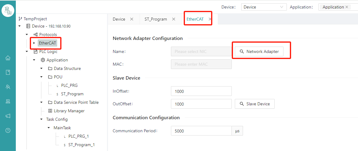
# 7.3 EtherCAT Master
- Adding a protocol bus
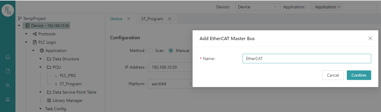
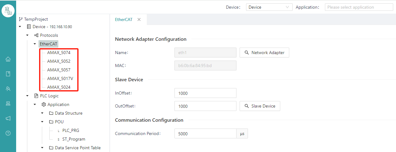
Right-click the communication protocol stack in the project tree on the left, select "EtherCAT Master Bus" from the list to add the EtherCAT master bus, and enter the bus name (no spaces between characters) in the pop-up box to confirm.
- Scan and add slaves
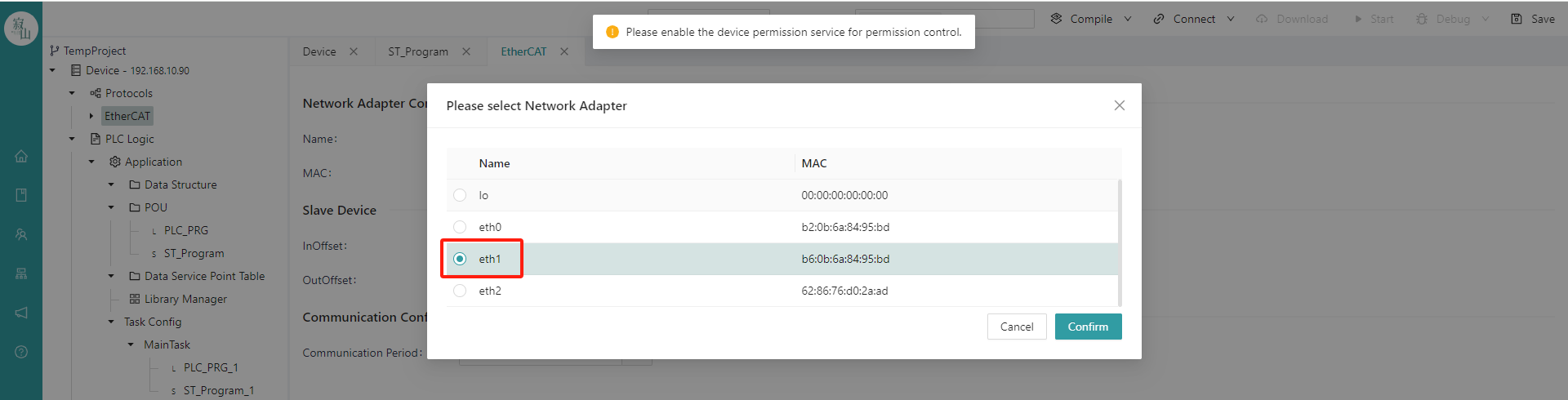
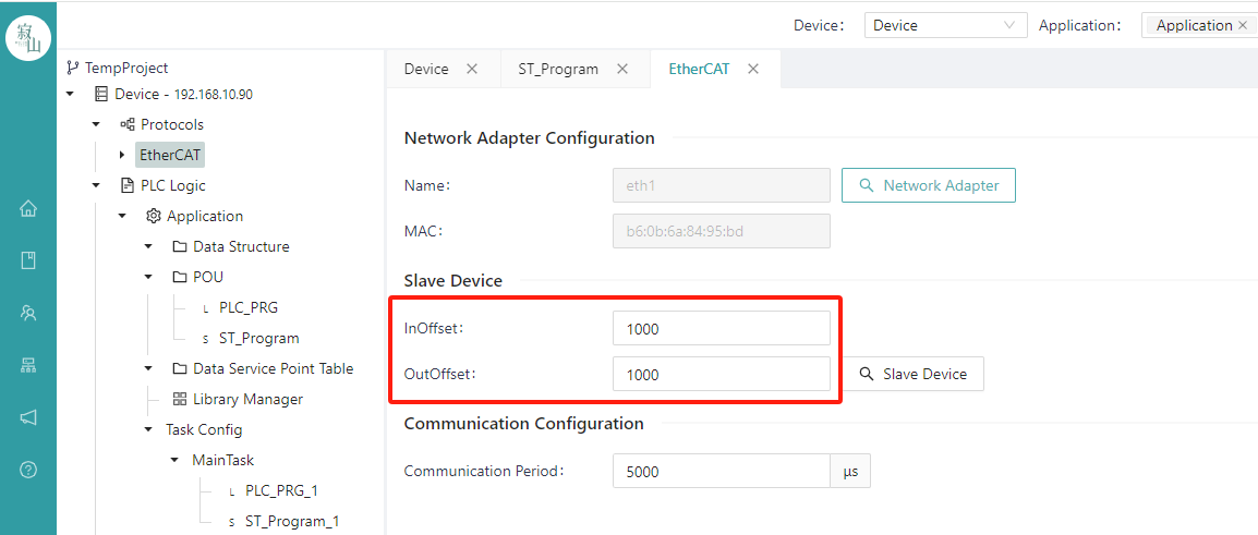
After the EtherCAT master bus is added, click the bus and select the NIC used by the bus on the right configuration page, click the "Network Configuration" button, select the target NIC in the NIC list of the device, and confirm.
After the NIC is selected, fill in the appropriate value in the offset box of the input/output area (EtherCAT is 1000 by default); The Tx-PDO logical point table of the slave corresponding to the offset of the input area is located at the starting position of the cache in the I region of the IEC address. The Rx-PDO logical point table corresponding to the slave offset in the output area is located at the start position of the cache in the Q area of the IEC address.
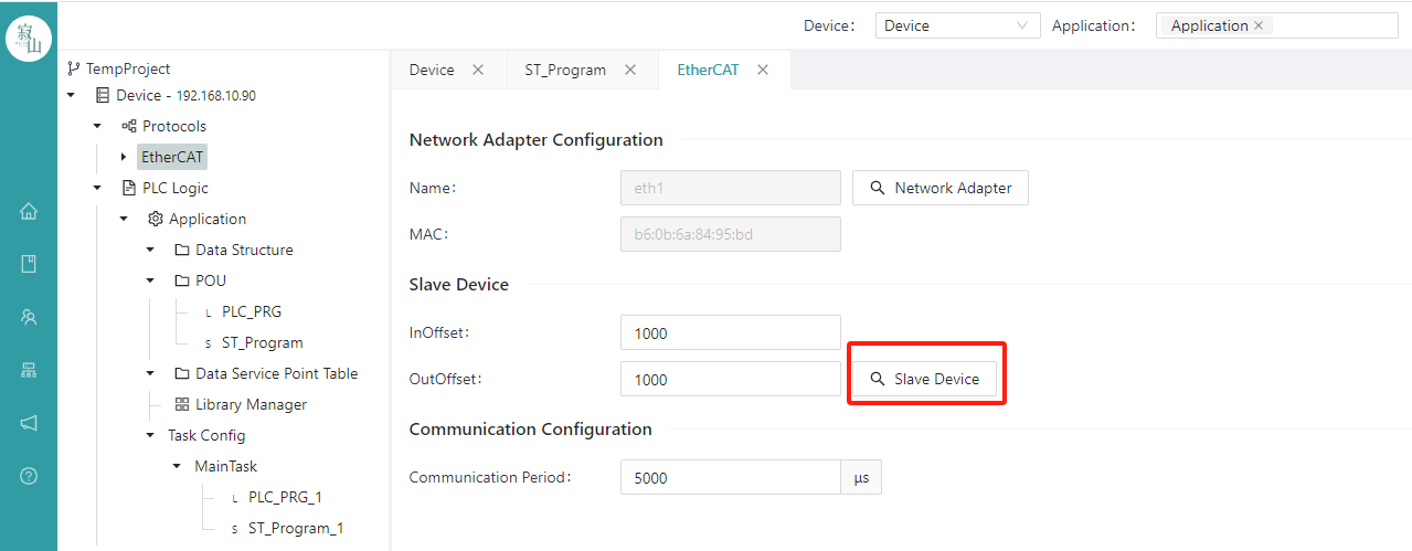
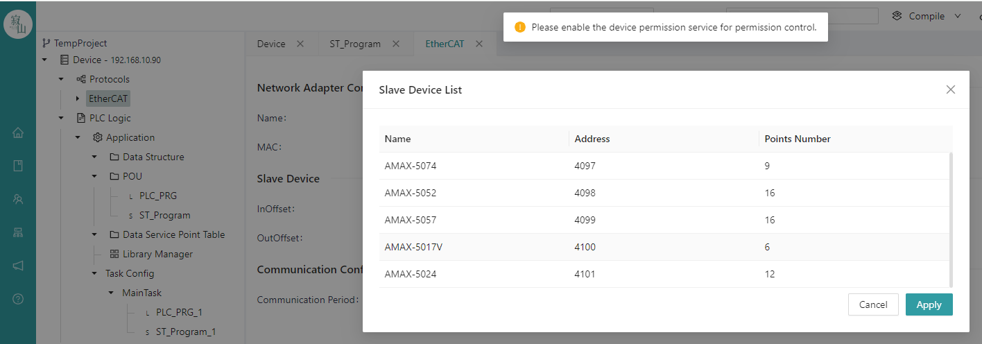
Click the "Slave Device" button to scan all slaves under the bus and display them in the form of a list, click the "Apply" button in the pop-up box of the slave equipment list to add the slave to the project, and display them as leaf nodes under the EtherCAT bus node in the project tree.
- Edit the slave
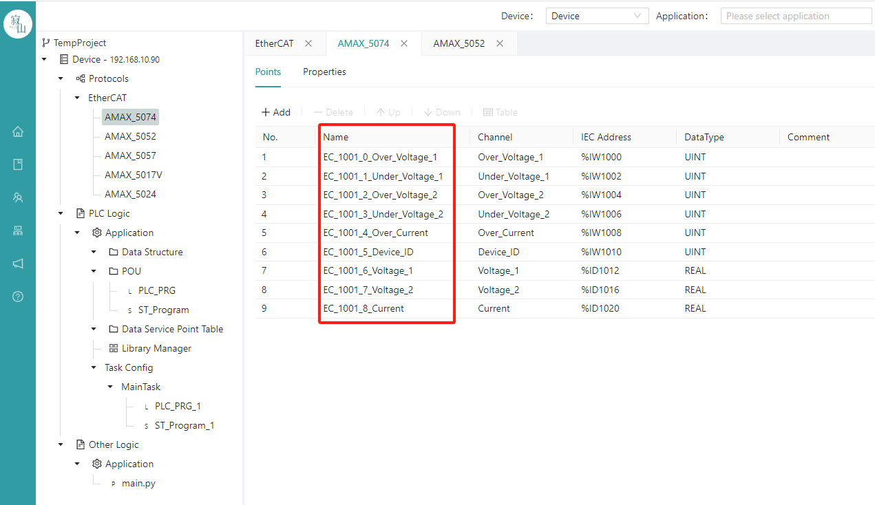
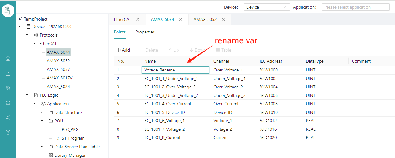
Click each slave to display the PDO point table owned by the slave on the right side of the slave information tab, including the variable name, channel name, IEC address, data type, etc., where each variable name is unique, and the user can rename the variable as needed.
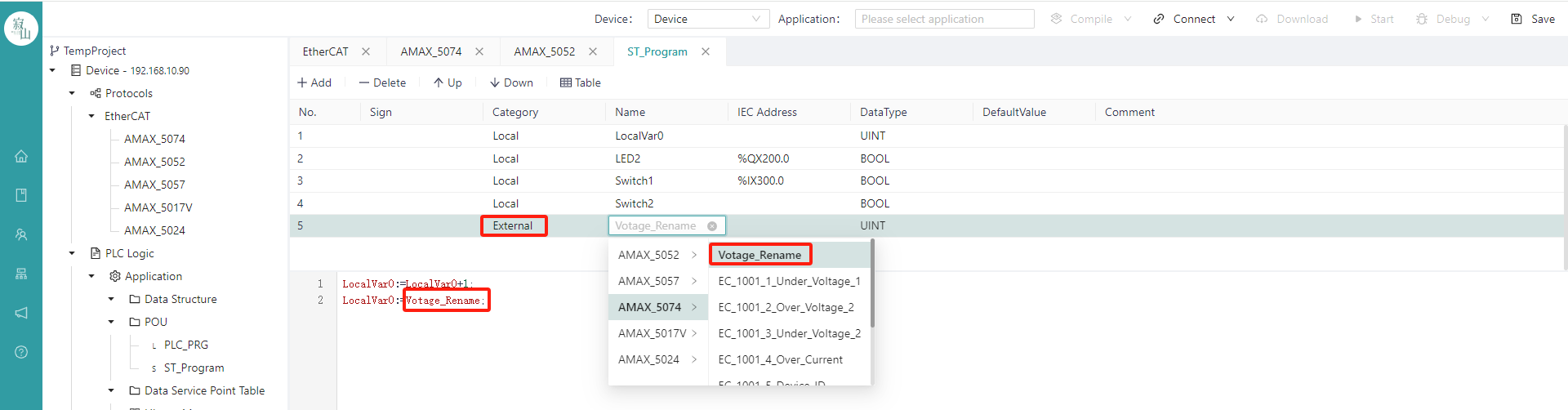
- Write applications that use slave variables
Add a variable in the edit area of the variable list in the POU, the category of the variable needs to be "External", click the variable "Name" area to select the variable needed. (Tips: Enter the key letter of the variable name to filter and improve efficiency); After the variables are selected, you can write the program in the program body editing area below.
Once the application is edited, select the device and application, and go through the "Compile", "Connect", "Download", and "Launch" steps to download the program to the target device to run.
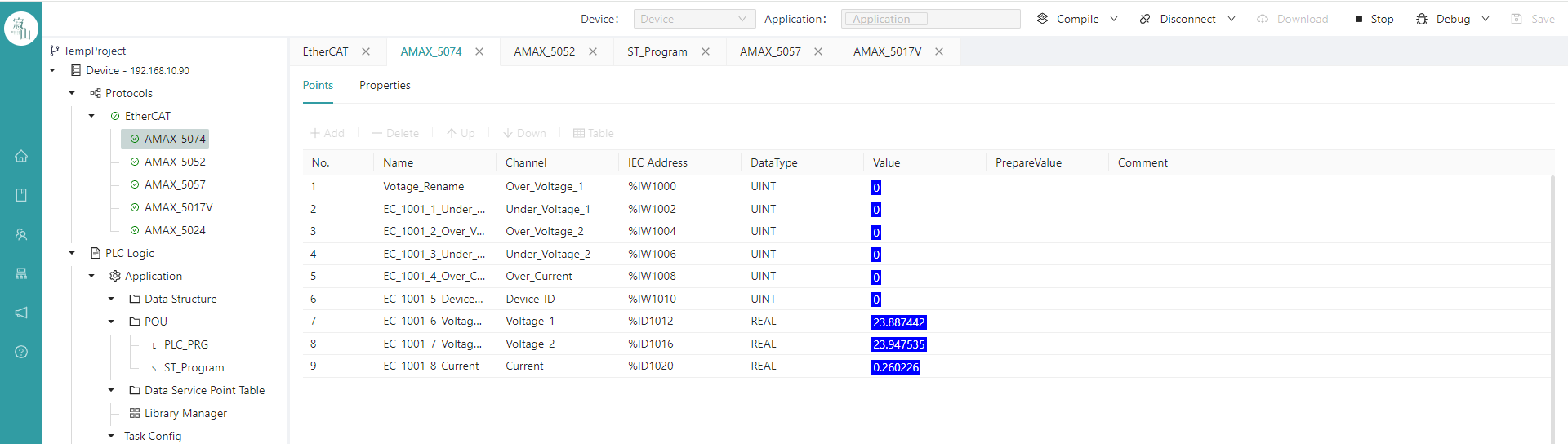
- Bus and slave status display
After the program is started, the real-time values of the variables can be displayed in the IDE, and the status of the EtherCAT bus and each terminal is also displayed in the project tree on the left, with a green icon indicating normal communication and a red icon indicating abnormal communication.
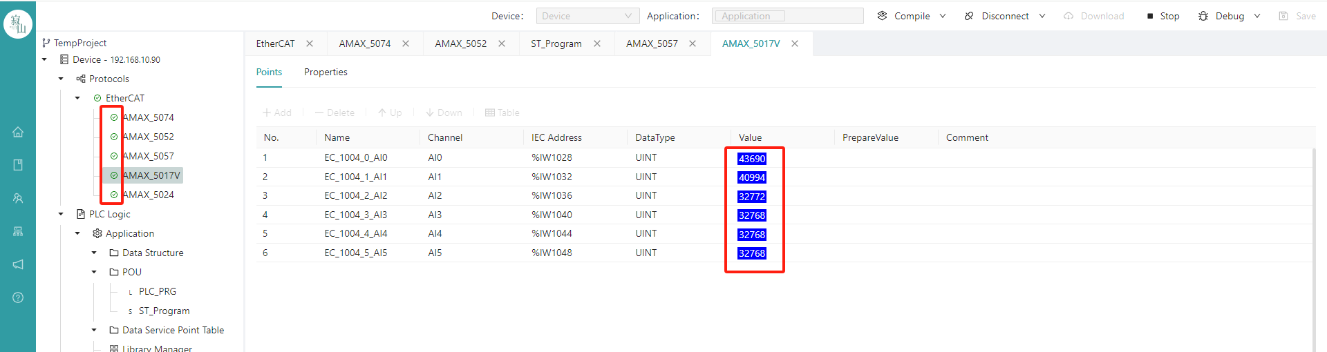
Click on the slave leaf node, and the real-time values of each variable are also displayed in the station table on the right.
# 7.4 Associate IO Variables Based on Communication Protocols
# 7.4.1 Modbus Variable Binding
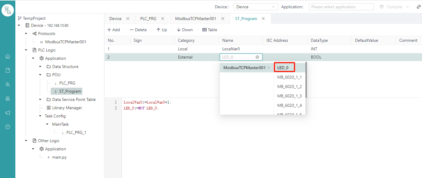
- Modbus Master variable binding
Modbus Master data operation
After the "Start Address" and "Quantity" parameters are configured, a point table of the corresponding number of points is automatically generated below, and then the user can bind the IEC variables with addresses in the application to the points in the table one by one. The "name" here can be changed freely according to the user's needs.
Modbus Master variable binding:
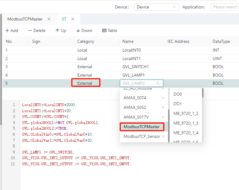
When programmatically defining a variable, select the "External" variable category and the editor will give you the name. Click the blank space of the "name" of each row to select the existing IEC variables in the project to bind to the row, the available variables have been filtered according to the data type, and the variables that do not match the data type or do not have the IEC address will not be displayed; Rows that are not bound to variables default to 0 for all data.
After binding a variable, you can access this variable to obtain the IO resources accessed by Modbus during the programming process.
Variable binding
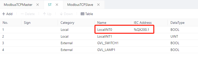
First, in the variable definition area of the program, correctly define the "category", "address", and name. Note: The address needs to conform to the IEC61131-3 syntax and match the type of variable to be bound.
Binding variables during Modbus Slave data operation:
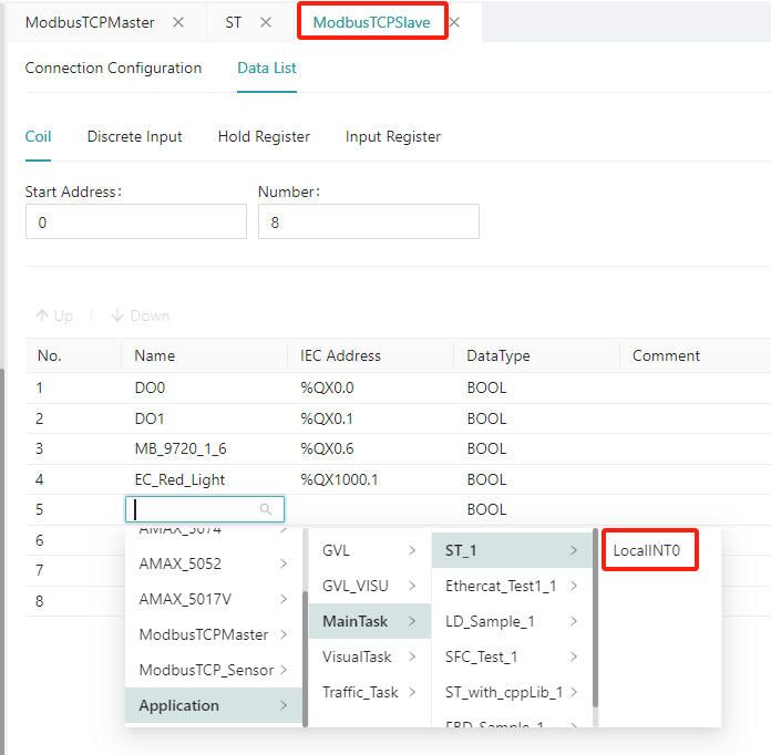
When configuring the Modbus Slave data operation, the user can map the variables in the slave to the variables with addresses in the program. If the type matches and is not already being used as another binding, the user can bind it.
In the same way, users can also "transparently" transmit the same type of variables in Modbus Master.